Over-voltage protection circuit for power converter

a protection circuit and power converter technology, applied in the direction of electric variable regulation, process and machine control, instruments, etc., can solve the problems of over-high output voltage and limited output voltag

Active Publication Date: 2006-11-07
SEMICON COMPONENTS IND LLC
View PDF7 Cites 47 Cited by
  • Summary
  • Abstract
  • Description
  • Claims
  • Application Information

AI Technical Summary

Benefits of technology

[0011]An over-voltage protection circuit used for power converter provides a proper protection during the period of feedback open loop or a higher supply voltage in accordance with present invention. Furthermore, through accumulating and counting the period of the fault conditions, the over-voltage protection circuit can avoid an improper protection for a larger output voltage needed in a very short period for the power converter.

Problems solved by technology

Thus an output voltage is limited in order to avoid the output voltage for the power converter is too high, which will cause an over-high output voltage during the period of feedback open loop or a higher supply voltage.

Method used


Image

  • Over-voltage protection circuit for power converter
  • Over-voltage protection circuit for power converter
  • Over-voltage protection circuit for power converter

Examples


Embodiment Construction

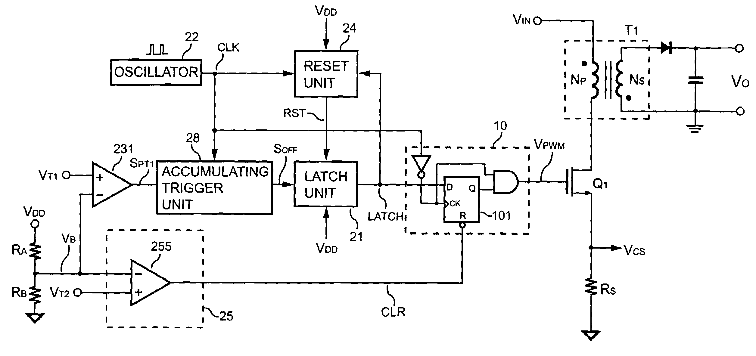
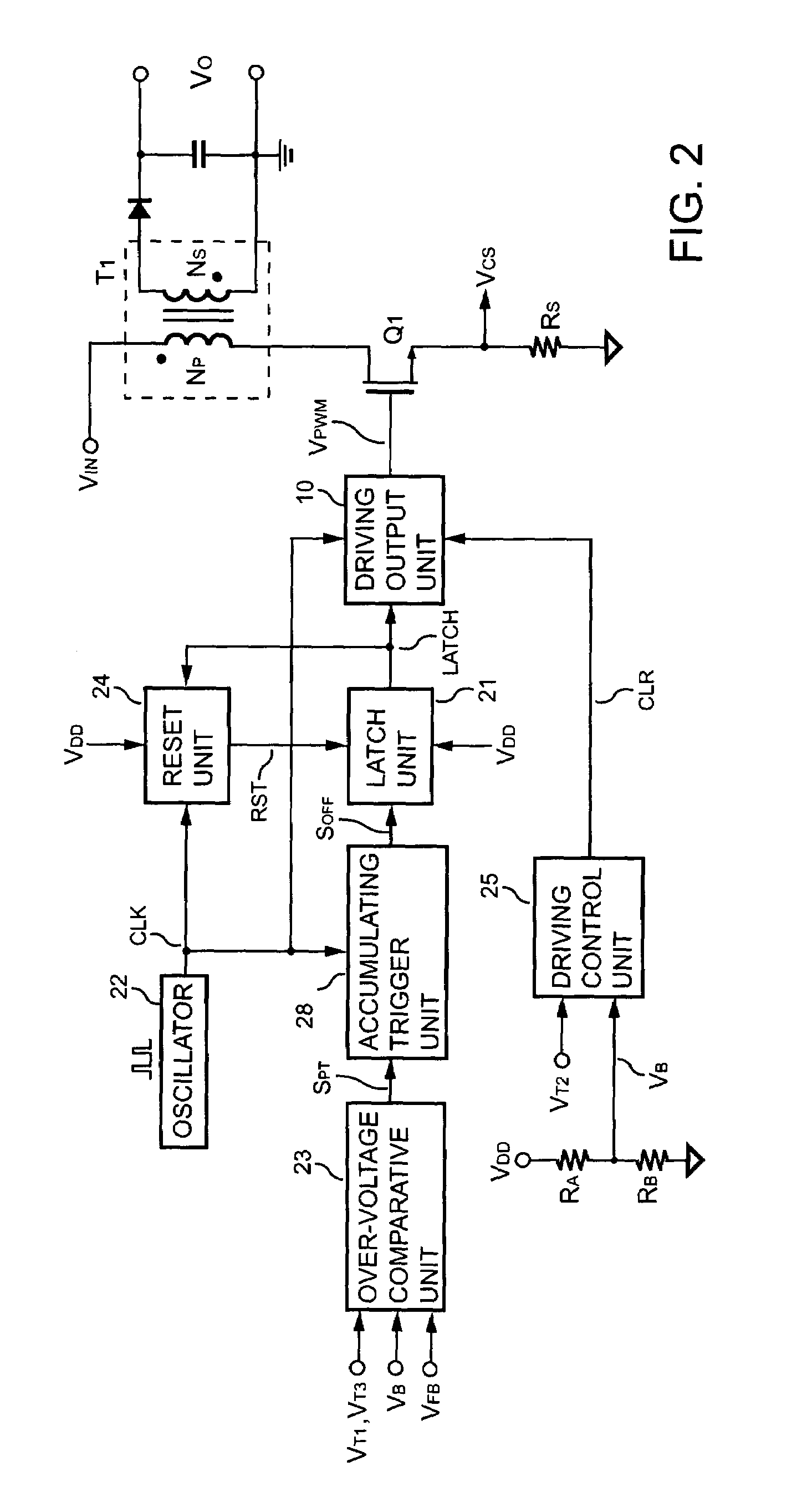
[0022]FIG. 2 shows a schematic diagram of a power converter according to the present invention. An over-voltage protection apparatus for a power converter comprises an over-voltage comparative unit 23. The over-voltage comparative unit 23 generates a protection signal SPT for receiving a sense signal through a voltage divider formed by a resistor RA and a resistor RB in response to the comparison between the sense signal and a threshold signal. An accumulating trigger unit 28 is connected to the over-voltage comparative unit 23 and an oscillator 22 for generating an off signal SOFF in response to a clock signal CLK and the protection signal SPT. The accumulating trigger unit 28 is used to accumulate and count the protection signal SPT and generates the off signal SOFF as a period of the protection signal SPT reaches a predetermined clock count. A latch unit 21 is connected to the accumulating trigger unit 28 for generating a latch signal LATCH in response to the off signal SOFF A dr...


PUM


Abstract

The present invention proposes an over-voltage protection apparatus for a power converter. The over-voltage protection apparatus has an oscillator outputting a clock signal. Simultaneously, by comparing a sense signal with a threshold signal, an over-voltage comparative unit outputs a protection signal to an accumulating trigger unit. Next, the accumulating trigger unit is accumulating and counting the protection signal in response to the clock signal. The accumulating trigger unit further outputs an off signal to a latch unit as a period of the protection signal reaches a predetermined clock count. In response to the off signal, the latch unit outputs a latch signal to a driving output unit for disabling a switching signal to a power switch. Therefore, the power switch is turned off, and the object of the over-voltage protection can be accomplished.

Description

BACKGROUND OF THE INVENTION[0001]1. Field of the Invention[0002]The present invention relates generally to an over-voltage protection circuit, and more specifically to the over-voltage protection circuit used for a switching mode power converter.[0003]2. Description of Related Art[0004]Various power converters have been widely used to provide a regulated voltage and current. For the sake of safety reasons, an over-voltage protection circuit must be provided to protect both the power converter itself and the system it powers. Thus an output voltage is limited in order to avoid the output voltage for the power converter is too high, which will cause an over-high output voltage during the period of feedback open loop or a higher supply voltage.[0005]FIG. 1 illustrates the topology of a conventional power converter. The power converter includes a switching controller U1 coupled to control the power converter. A resistor RST and a capacitor CST provide an initial power source to start up...

Claims


Application Information

Patent Timeline
Patent Type & Authority Patents(United States)
IPC IPC(8): H02H7/122
CPCH02H7/122H02M3/33507H02M1/32
Inventor YANG, TA-YUNG
Owner SEMICON COMPONENTS IND LLC
Why Eureka
Try Eureka