
Device with time indicating means

a technology of time-indicating means and indicators, which is applied in the field of indicators devices, can solve the problems of uncertain reference to the hour, relatively expensive devices most suited for use as re-useables, and achieve the effects of reducing the risk of overdosing, preventing any overdosing, and running the risk of hypoglycaemia

Active Publication Date: 2006-11-07
NOVO NORDISK AS
View PDF12 Cites 313 Cited by
  • Summary
  • Abstract
  • Description
  • Claims
  • Application Information

AI Technical Summary

Benefits of technology

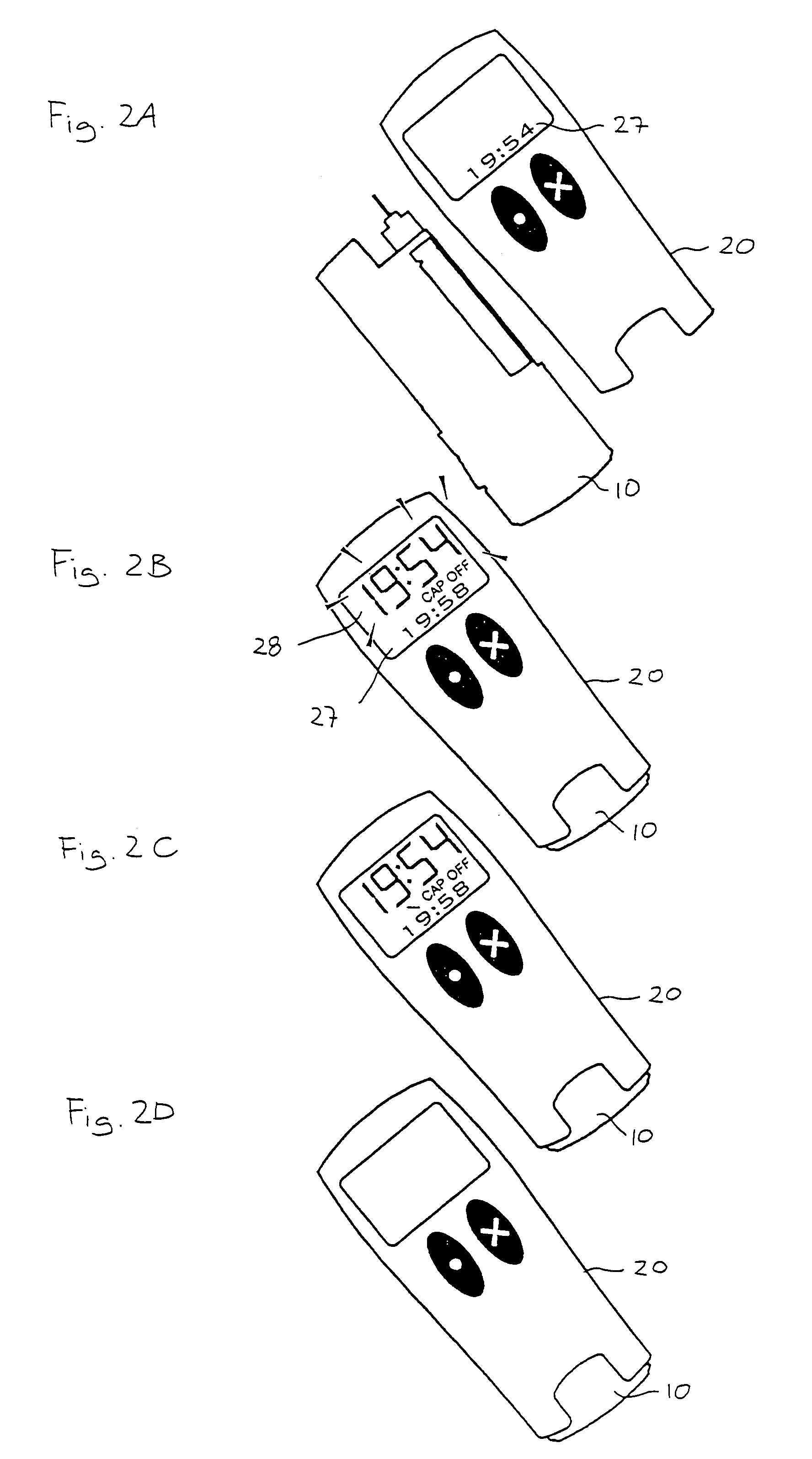
[0058]In order to prevent any overdosing and thereby running the risk of hypoglycaemia, the above-described timer device is set-up to assume that an injection has taken place as late as possible, i.e. when the doser was inserted in the cap after 73 minutes. As cancellation or toggle of the automatic reset action requires a positive action by the user, the risk of overdosing is reduced.
[0059]However, in case underdosing is to be prevented, which may be the case in treatment with e.g. growth hormone (GH), the timer device may be set up to assume that an injection has (i) not taken place although it was

Problems solved by technology

However, in a world where people in a short time may cross between different time zones, and the hours in the time zones even may shift from summer to winter time, a reference to the hour may be uncertain.
Here the count down is more adequate but has the drawback that unless you are ready to take an injection immediately when the alarm sounds you will have a new time account to handle, e.g. for how long an interval was the alarm set and how long time has passed from the sound of the alarm till the injection is actually made.
In these devices the dose setting and injection mechanism are formed integrally with the electronic control, clock and display means necessary for providing the desired information, this resulting in a relatively expensive device most suited for use as a re-useable or durable device, e.g. a device which can be refilled with a drug such as a prefilled cartridge.

Method used


Image

  • Device with time indicating means
  • Device with time indicating means
  • Device with time indicating means

Examples


Embodiment Construction

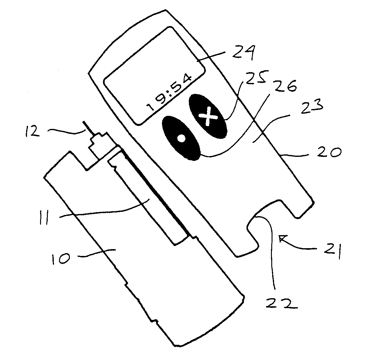
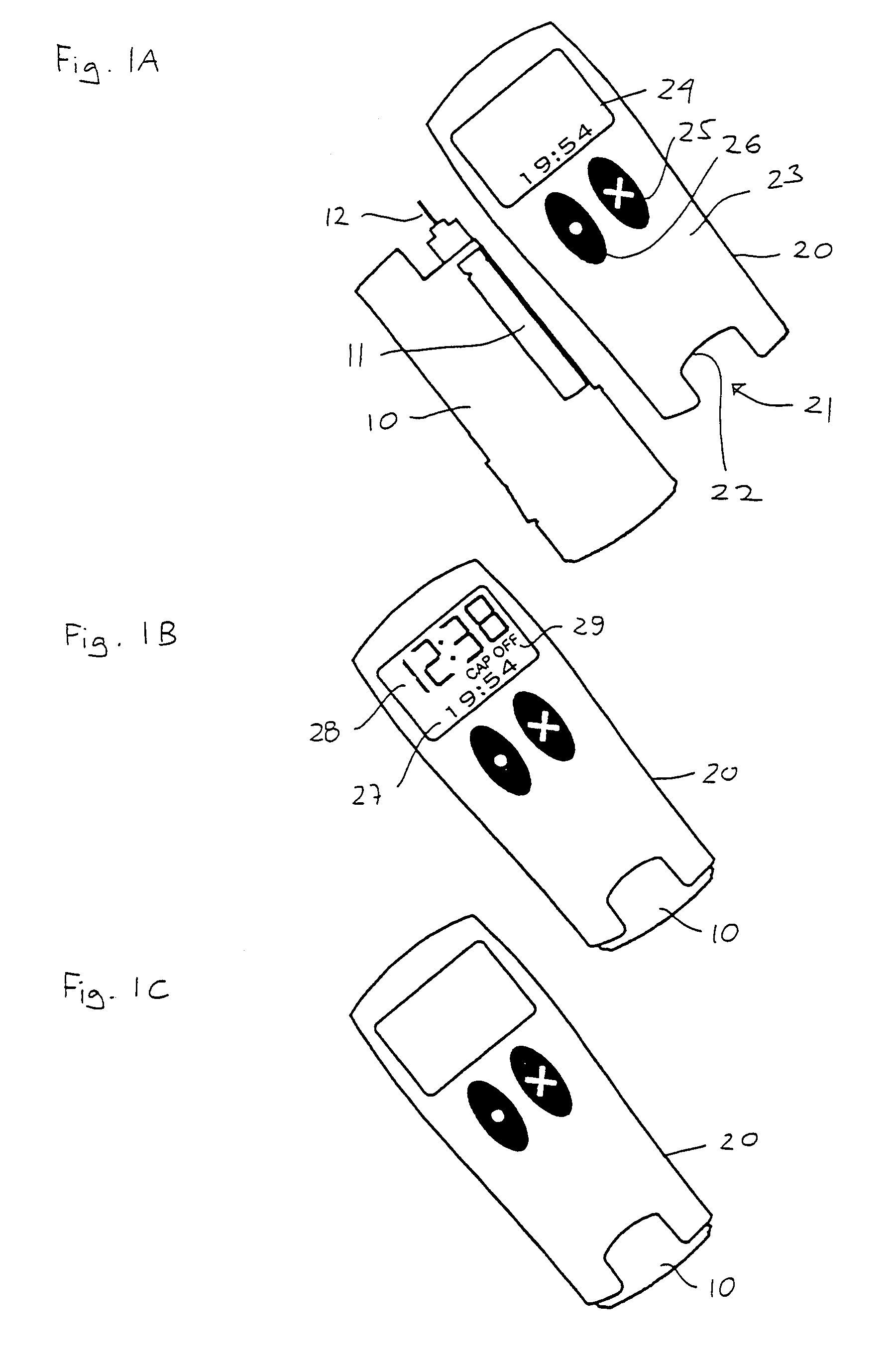
[0044]FIG. 1A shows an injection device for use by a patient for medical self treatment, such a device also being known as a “pen” or a “doser” device.

[0045]The injection device comprises a first device portion 10 in the form of a “doser” for performing a subcutaneous injection of a medicament and a second device portion 20 in the form of a cap configured to be attached on the doser. The doser comprises a reservoir 11 containing a medicament, a distal end of the reservoir being provided with an injection needle 12 providing fluid communication with the interior of the reservoir, a dose setting mechanism (not shown) allowing the user to set a desired dose the medicament to be injected, and driving means (e.g. a push button, not shown) for expelling medicament from the reservoir in accordance with the set dose.

[0046]The cap comprises an interior space with a distal opening 21 allowing the doser to be received there within (see FIG. 1B), the distally facing rim portion defining the ope...


PUM


Abstract

The invention relates to a timer device capable of performing one or more control actions in response to the time lapsed since a user initiated action took place. The timer device comprises contact means operatable between two conditions, timer means, and means for storing first and second time stamps. The device further comprises control means for setting a first time stamp in response to the contact means being operated between first and second conditions, setting a second time stamp in response to the contact means being operated between the second and first conditions, calculating the time elapsed between the two time stamps, comparing the elapsed time with a preset time value, and performing a control action if the elapsed time is greater than the preset time value.

Description

CROSS REFERENCE TO RELATED APPLICATIONS[0001]This application claims priority under 35 U.S.C. 119 of European application no. EP 02388054.5 filed Aug. 19, 2002 and U.S. provisional application No. 60 / 398,300 filed Jul. 23, 2002, the contents of both are fully incorporated herein by reference.FIELD OF THE INVENTION[0002]The present invention relates to an indicator device capable of performing one or more control actions in response to the time lapsed since a user initiated action took place. In exemplary embodiments the indicator device is adapted to engage a device capable of performing a user initiated action, especially a medical injection device adapted to deliver a given amount of an active substance such as insulin to the user.BACKGROUND OF THE INVENTION[0003]To patients, such as diabetics, who have to frequently inject themselves with a drug, it is necessary to keep account of when an injection has to be made or when an injection last time took place. This information could b...

Claims


Application Information

Patent Timeline
IPC IPC(8): G04F8/00G04F10/00A61J7/04A61M5/178A61M5/20A61M5/28A61M5/31G04B25/06G04F1/00G04G15/00
CPCA61J7/0481A61M5/178A61M5/20G04B25/06G04F1/005A61J2007/049A61M5/28A61M5/3129A61M2005/3125A61M2205/50A61M2205/581A61J7/0436
Inventor SKYGGEBJERG, OLECHRISTENSEN, LARS HOFMANNPANDURO, RASMUSBJORLIG, NINALAV, STEFFENWEBEN, BARRYALVAREZ-ICAZA, MANUELSYME, STEVEN
Owner NOVO NORDISK AS
Learn More