Power-assist brake system equipped with adhesive joint and method for mounting same

a technology of brake system and adhesive joint, which is applied in the direction of brake system, machine/engine, manufacturing tools, etc., can solve the problems of more difficult connection, loss of correct positioning of brake servo or at the very least its correct positioning facing the aperture in the bulkhead, and cost and coordination, and achieve the effect of correct tightening torque and quick removal

Active Publication Date: 2010-09-02
ROBERT BOSCH GMBH
View PDF14 Cites 0 Cited by
  • Summary
  • Abstract
  • Description
  • Claims
  • Application Information

AI Technical Summary

Benefits of technology

[0003]It is therefore necessary, in order to ensure the comfort and safety of the user of the vehicle, for the division created by the bulkhead between the engine compartment and the passenger compartment to be insulated as well as possible. It is therefore necessary to avoid any gap in the vicinity of an aperture or where a component passes through the bulkhead.
[0004]Thus, the seal positioned against the bulkhead, usually on the engine compartment side, is designed to eliminate these gaps. It avoids drafts inside the passenger compartment but also prevents any leaking engine exhaust gas or any emissions from any oil that has dropped onto the engine block, from distracting or even intoxicating the driver of the vehicle with toxic vapors.
[0005]This seal also makes it possible, when the vehicle is driving through a heavy storm or when the vehicle is being washed with a pressure washer, to guarantee that the passenger compartment will remain dry and free of moisture.
[0006]This seal also provides good acoustic insulation, insulating the passenger compartment from engine noise or vibration transmitted through the bulkhead.
[0015]In the solution of the invention, the protective film is designed to be removed quickly in a single movement consistent with the throughput of the assembly line without the seal tearing and without the slightest scrap of protective film remaining on the face that is to be offered up to the bulkhead. In addition, the adhesion between the seal and the bulkhead is intended to support the weight of a brake servo weighing around 2 to 3 kilograms. Thus, the operator has the opportunity and the time needed to move around from the engine compartment side to the passenger compartment side without the help of a colleague and without running the risk of losing the brake servo or its alignment facing the aperture in the bulkhead.
[0016]The solution also makes it possible to maintain the correct tightening torque used to tighten the screws onto the attachment studs of the brake servo while at the same time achieving correct acoustic, thermal and mechanical sealing of the seal.

Problems solved by technology

The need for two operators in order to perform this single operation on the vehicle assembly line gives rise to problems associated with cost and coordination.
This presents problems because there is a high risk that the brake servo or at the very least its correct positioning facing the aperture in the bulkhead will be lost while the operator is moving around to the other side of the bulkhead.
Now, having the brake servo positioned only approximately on the bulkhead can not only make it more difficult to connect it to the pedal box control system in the passenger compartment, but can also lead to gaps at the junction with the bulkhead, these gaps being detrimental to the sealing of the engine compartment with respect to the passenger compartment.
The problem is to successfully mount a brake servo with a seal that will allow a single operator to attach the brake servo correctly to the pedal box control in the passenger compartment in the knowledge that the brake servo will still be offered up to the bulkhead from the engine compartment side.

Method used


Image

  • Power-assist brake system equipped with adhesive joint and method for mounting same
  • Power-assist brake system equipped with adhesive joint and method for mounting same
  • Power-assist brake system equipped with adhesive joint and method for mounting same

Examples


Embodiment Construction

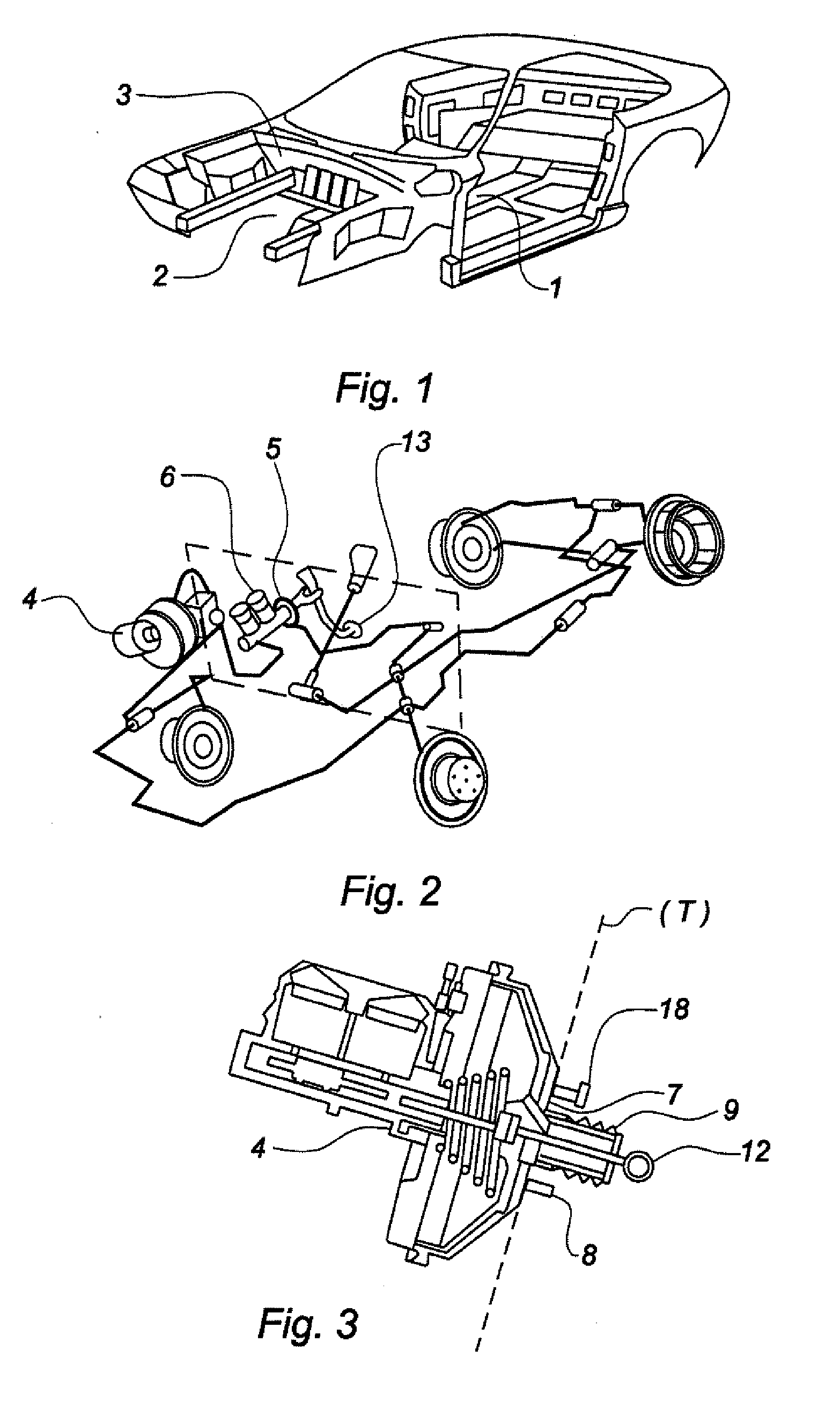
[0023]FIG. 1 shows a vehicle such as it might appear in the assembly phase on an assembly line. There are three regions that differ from one another: the passenger compartment 1 determining the interior structure of the vehicle, the engine compartment 2 housing the engine and the main dynamic functions of the vehicle, and, between these two, the bulkhead 3.

[0024]The bulkhead 3 is in the form of a sheet metal partition inclined toward the passenger compartment. It begins at the base of the engine block support and is angled gradually as far as the base of the vehicle windscreen (windshield).

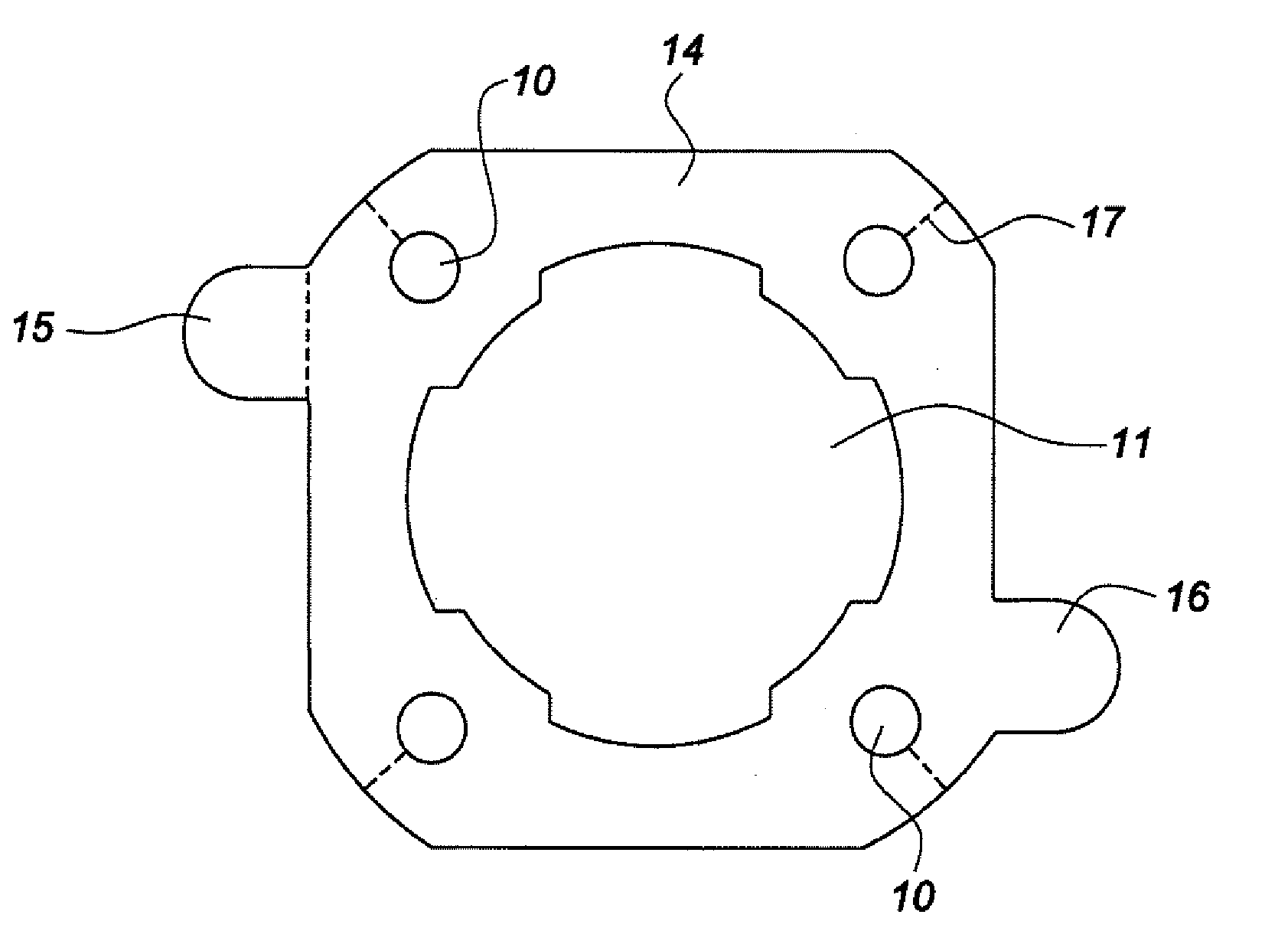
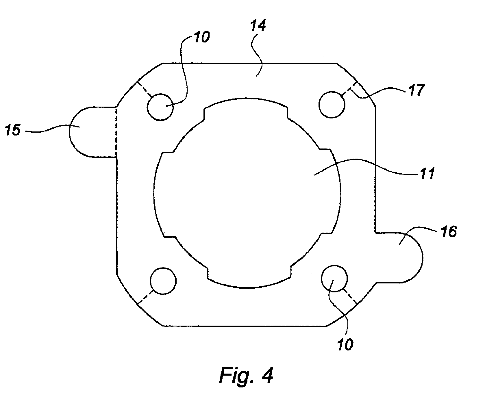
[0025]FIG. 2 denotes the main devices involved in the invention. It shows the brake servo 4 on the engine compartment 2 side and the pedal box control 5 on the passenger compartment 1 side, here shown with a master cylinder 6. FIG. 3 depicts a brake servo 4 with its bearing surface 7 for resting against the bulkhead 3 and the inclined plane (T) that corresponds to the surface of the bulkhead 3. Th...


PUM

PropertyMeasurementUnit
weightaaaaaaaaaa
thicknessaaaaaaaaaa
densityaaaaaaaaaa

Abstract

In order to allow a single operator on a vehicle assembly line to attach a brake servo to a bulkhead by moving round from the engine compartment side to the passenger compartment side, use is made of a brake servo fitted with an adhesive and insulating seal (14).This seal has two adhesive faces and each of the two adhesive faces has a protective film provided with a tab (15, 16); each protective film is of a distinctive color. One of the two protective films has cuts (17) along the holes (10, 11) in the seal, these cuts being intended to make it easier for the protective film to be removed as the brake servo is mounted against the bulkhead.

Description

BACKGROUND AND SUMMARY OF THE INVENTION[0001]The subject of the present invention is a brake servo positioned against a bulkhead (dash panel) of a vehicle. Another subject of the invention is a method of mounting this brake servo against a bulkhead. The object of the invention is to make such a brake servo located in the engine compartment of a vehicle easier to mount and to connect to a brake pedal via a pedal box control located on the other side of the bulkhead, inside the passenger compartment of the vehicle.[0002]The field of application of the invention is that of the seals found on a bulkhead when a vehicle is being assembled on a production line. These seals are needed whenever a cable or a moving part such as a rod or a lever is passed through an aperture in the bulkhead, from the engine compartment to the passenger compartment of the vehicle, in order to seal said aperture.[0003]It is therefore necessary, in order to ensure the comfort and safety of the user of the vehicle...

Claims


Application Information

Patent Timeline
Patent Type & Authority Applications(United States)
IPC IPC(8): F16J15/02B23P17/04
CPCY10T29/49947B60T13/567
Inventor LHUILLIER, LAURENTBENOIT, ALAIN
Owner ROBERT BOSCH GMBH
Why Eureka
Try Eureka