
Pneumatic tire for heavy load

Active Publication Date: 2014-01-02
BRIDGESTONE CORP
View PDF6 Cites 16 Cited by
  • Summary
  • Abstract
  • Description
  • Claims
  • Application Information

AI Technical Summary

Benefits of technology

This patent text describes a solution for improving the traction and braking performance of dump trucks used in mines. By designing the tread of the truck with a shallow groove and a specific width, the edges of the tire can better hold mud and increase in width, resulting in better traction and braking performance. This solution also helps prevent the risk of not achieving the desired edge effect with the shallow groove. Overall, this patent aims to enhance the efficiency and reliability of dump trucks in muddy areas.

Problems solved by technology

In this case, the soft clay layer between the tread surface and the hard ground makes it difficult to effectively transmit traction force and braking force to the road surface.
Mud then accumulates between the trailing edge portion and the road surface, resulting in an insufficient traction effect of the block edge at the trailing edge portion of the block on such road surfaces, causing the problem of the vehicle slipping upon application of a breaking force.
This problem reduces the running speed in dump trucks and the like used in mines, for example, leading to delays in transport by such dump trucks and running the risk of a deterioration in operation efficiency.
If the width direction component is increased by merely adding grooves extending in the tread width direction to the tread surface to partition the blocks, however, the mud from the soft clay layer remaining between the block surface and the road surface in the contact patch causes the tire to slip, thereby preventing the anti-slip effect from being achieved to the desired degree.

Method used


Image

  • Pneumatic tire for heavy load
  • Pneumatic tire for heavy load
  • Pneumatic tire for heavy load

Examples


example 1

[0070]Next, the results of a performance assessment of sample pneumatic tires according to the present invention are described. The size of each sample tire was 27.00 R49.

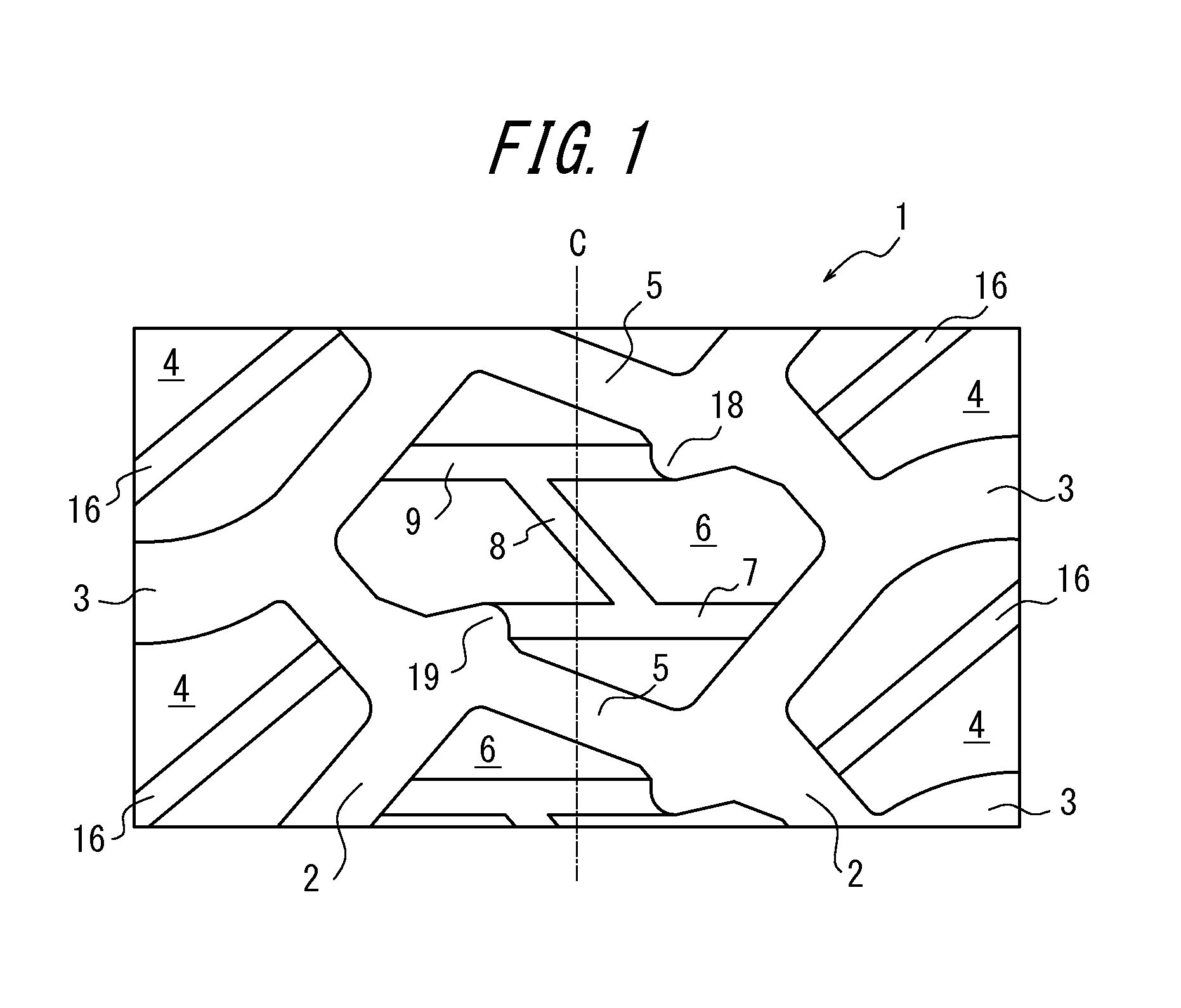
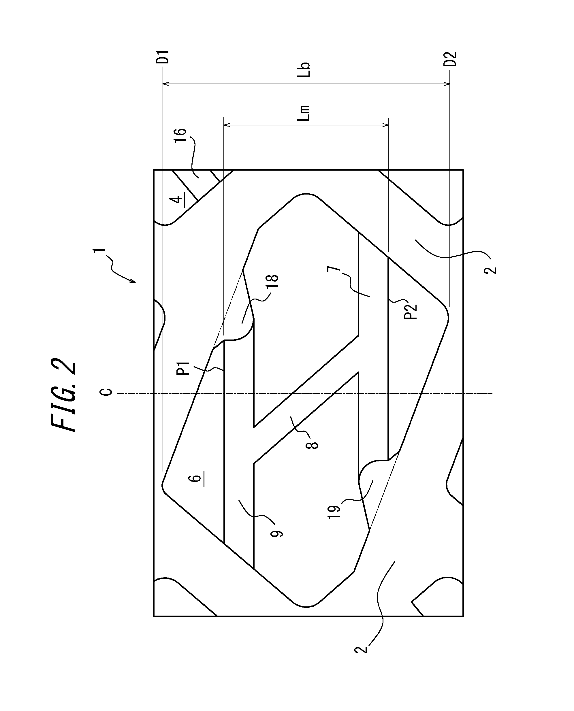
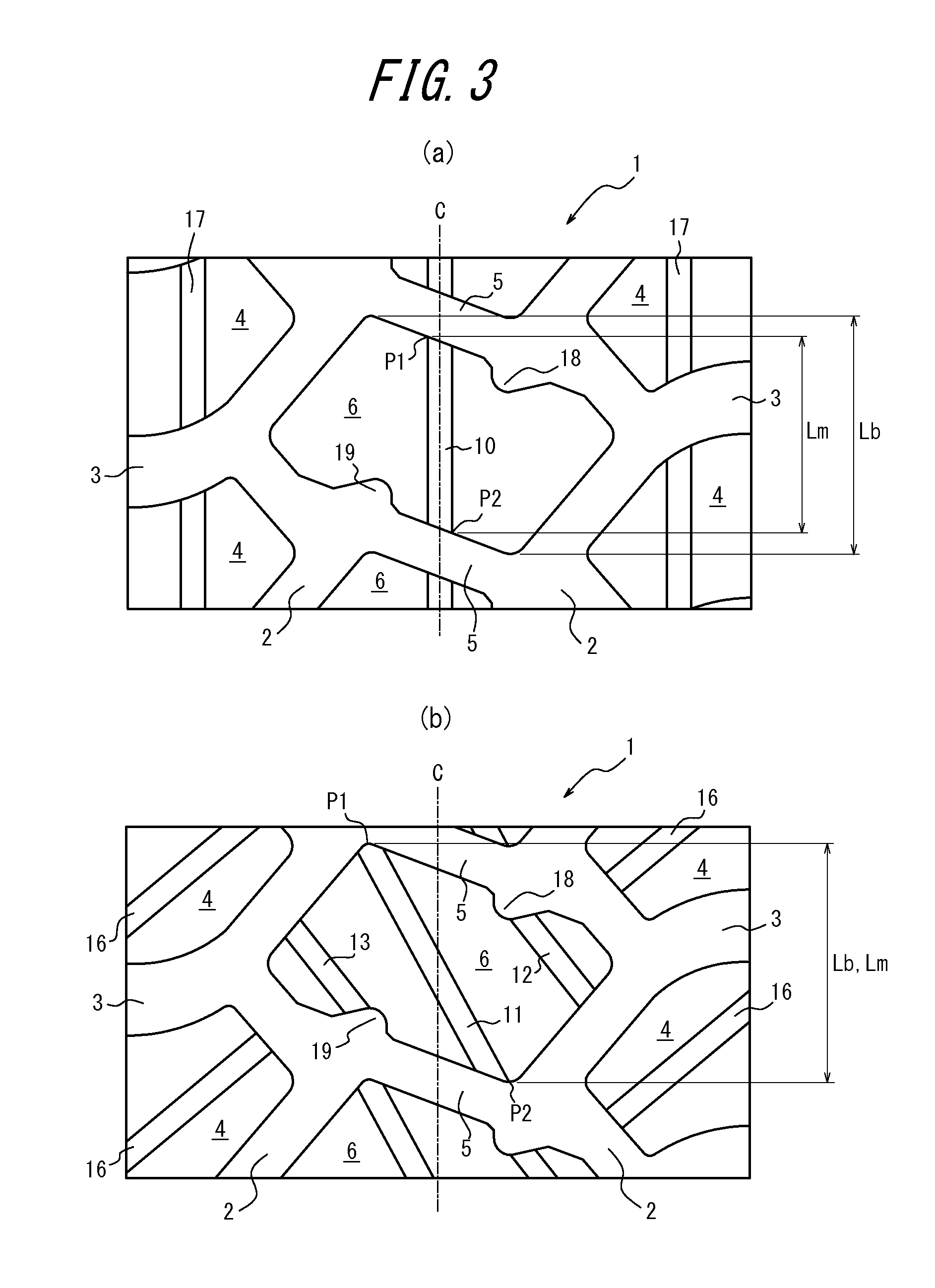
[0071]Example Tires 1-10 had the patterns illustrated in FIG. 3(a), FIG. 7, FIG. 8, FIG. 4(b), FIG. 4(a), FIG. 3(b), FIG. 1, and FIG. 5. The Comparative Tire had the pattern illustrated in FIG. 6.

[0072]Each of these sample tires was mounted on a dump truck and run over a route with identical conditions under settings conforming to TRA. After a predetermined time had elapsed, the distance the vehicle had progressed (travel distance) was measured by GPS, and the slip ratio was calculated by comparison with the distance calculated based on the number of tire revolutions (revolution distance). The slip ratio can be calculated with the following equation.

slip ratio=(revolution distance−travel distance) / travel distance

[0073]Tables 1 and 2 show the results along with the specifications for each sample tire. Note that the ...


PUM


Abstract

A pneumatic tire for heavy load has a tread, circumferential grooves (2) extending continuously in the tread circumferential direction, transverse grooves (5) opening to the circumferential grooves (2) adjacent each other in the tread width direction, and a block (6) defined by the circumferential grooves (2) and the transverse grooves (5) on a surface (1) of the tread. The block (6) is provided with one or more shallow grooves (7-9) having an average groove depth shallower than a groove depth of the circumferential grooves (2) adjacent to the block (6). The average groove depth of the shallow grooves (7-9) is greater than 20% and less than 80% of the groove depth of the circumferential grooves (2). At least one of the shallow grooves (7-9) opens to at least one of the transverse grooves (5) and the circumferential grooves (2) adjacent to the block (6).

Description

TECHNICAL FIELD[0001]The present invention relates to a pneumatic tire for heavy load including, on a tread surface, blocks defined by at least two circumferential grooves extending continuously in a tread circumferential direction and transverse grooves opening to the circumferential grooves adjacent in the tread width direction.BACKGROUND ART[0002]A conventional example of this type of heavy load tire, used in dump trucks and the like, is recited in Patent Literature 1. Dump trucks, which may be used at locations such as construction sites and mines, are sometimes driven over road surfaces such as muddy areas on which a soft clay layer several centimeters thick has formed on hard ground after a rain.CITATION LISTPatent Literature[0003]PTL 1: JP10278513ASUMMARY OF INVENTION[0004]When driven on a road surface with such a clay layer formed thereon, the tread portion of the tires mounted on a vehicle does not completely sink into the clay layer, yet the tires rotate with load applied ...

Claims


Application Information

Patent Timeline
IPC IPC(8): B60C11/11
CPCB60C11/11B60C11/0311B60C11/0316B60C11/1369B60C2011/0351B60C2011/0362B60C2200/06B60C2200/065
Inventor NAKAMURA, SHINSUKE
Owner BRIDGESTONE CORP
Learn More