

System and method for router central arbitration
a router and central arbitration technology, applied in the field of optical communication networks, can solve the problems of limiting the size of the electrical crossbar to tens of ports at a maximum, ip routers have been unable to take advantage of optical switch technology, and the scalability limitations of electrical crossbars, so as to achieve the effect of maximizing the number of connections through optical switch
- Summary
- Abstract
- Description
- Claims
- Application Information
AI Technical Summary
Benefits of technology
Problems solved by technology
Method used
Image

Examples
Embodiment Construction
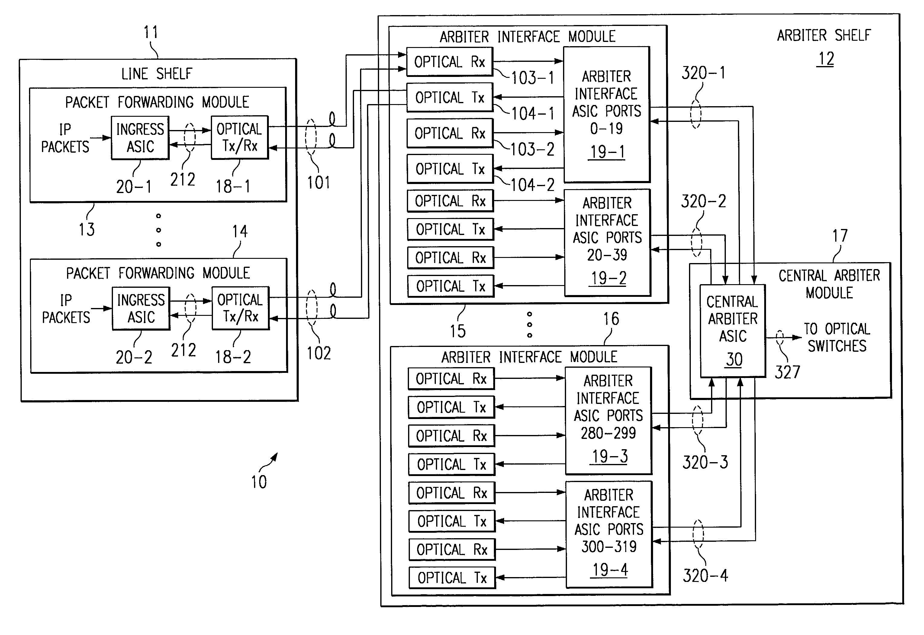
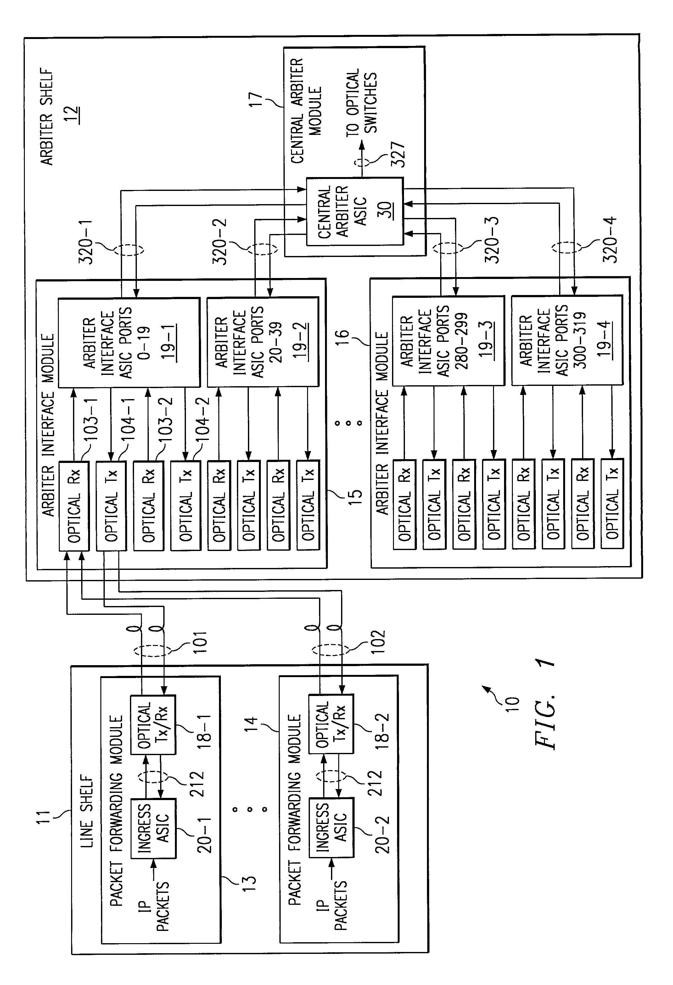
[0022]FIG. 1 is an overview logic diagram of a router arbitration structure, in accordance with an embodiment of the present invention. A line shelf 11 contains multiple packet forwarding modules 13 and 14 in the present example. Generally multiple line shelves are remotely distributed through a router system. Packet forwarding modules 13, 14 include respective ingress ASICs 20-1 and 20-2 interconnected with respective optical transceivers 18-1 and 18-2 through electrical links 212. Transceiver 18-1 is interconnected through optical links 101 with an optical receiver 103-1 and an optical transmitter 104-1 contained in an arbiter interface module (AIM) 15 located in an arbiter shelf 12. Also contained in AIM 15 and interconnected with optical receiver 103-1 and optical transmitter 104-1 is an arbiter interface ASIC 19-1. Arbiter shelf 12 further includes a central arbiter ASIC 30 within a central arbiter module 17. Central arbiter ASIC 30 is interconnected with AIM 19-1, 19-2 through...
PUM
 Abstract
Description
Claims
Application Information