

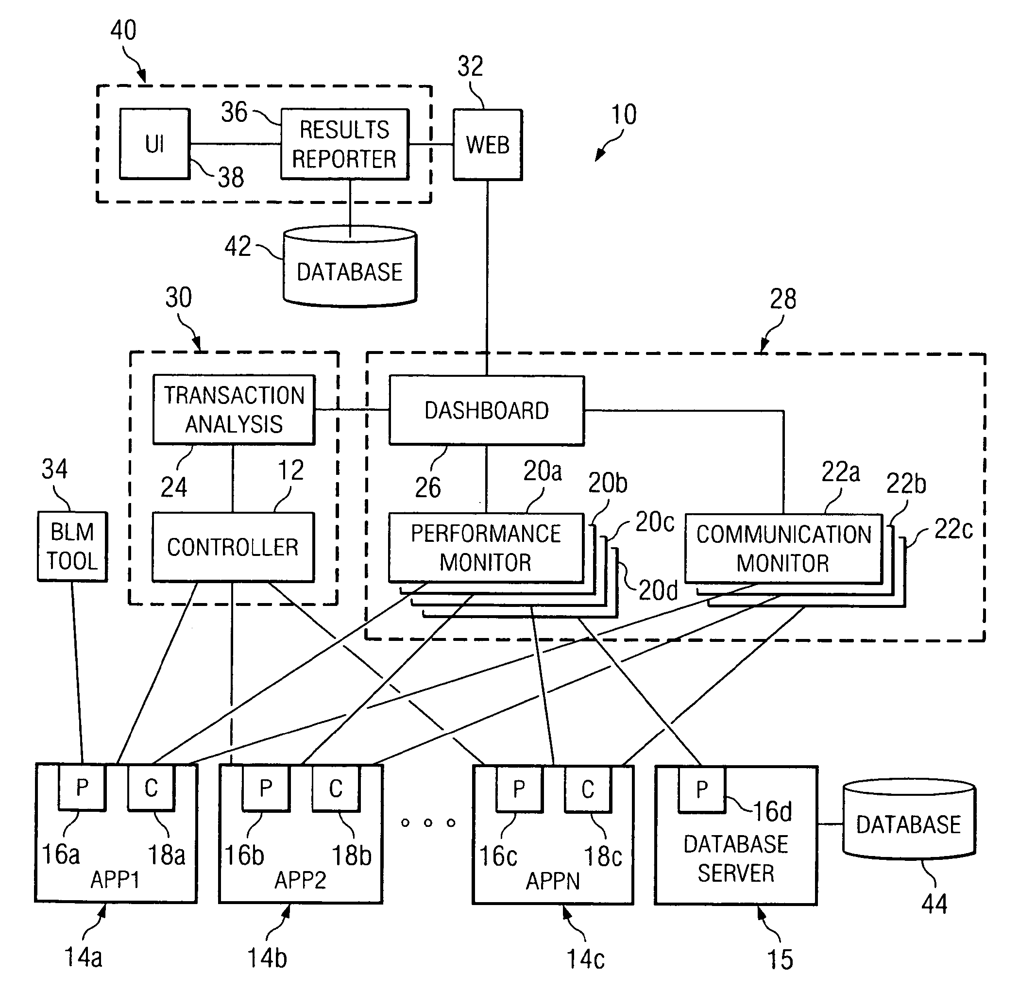
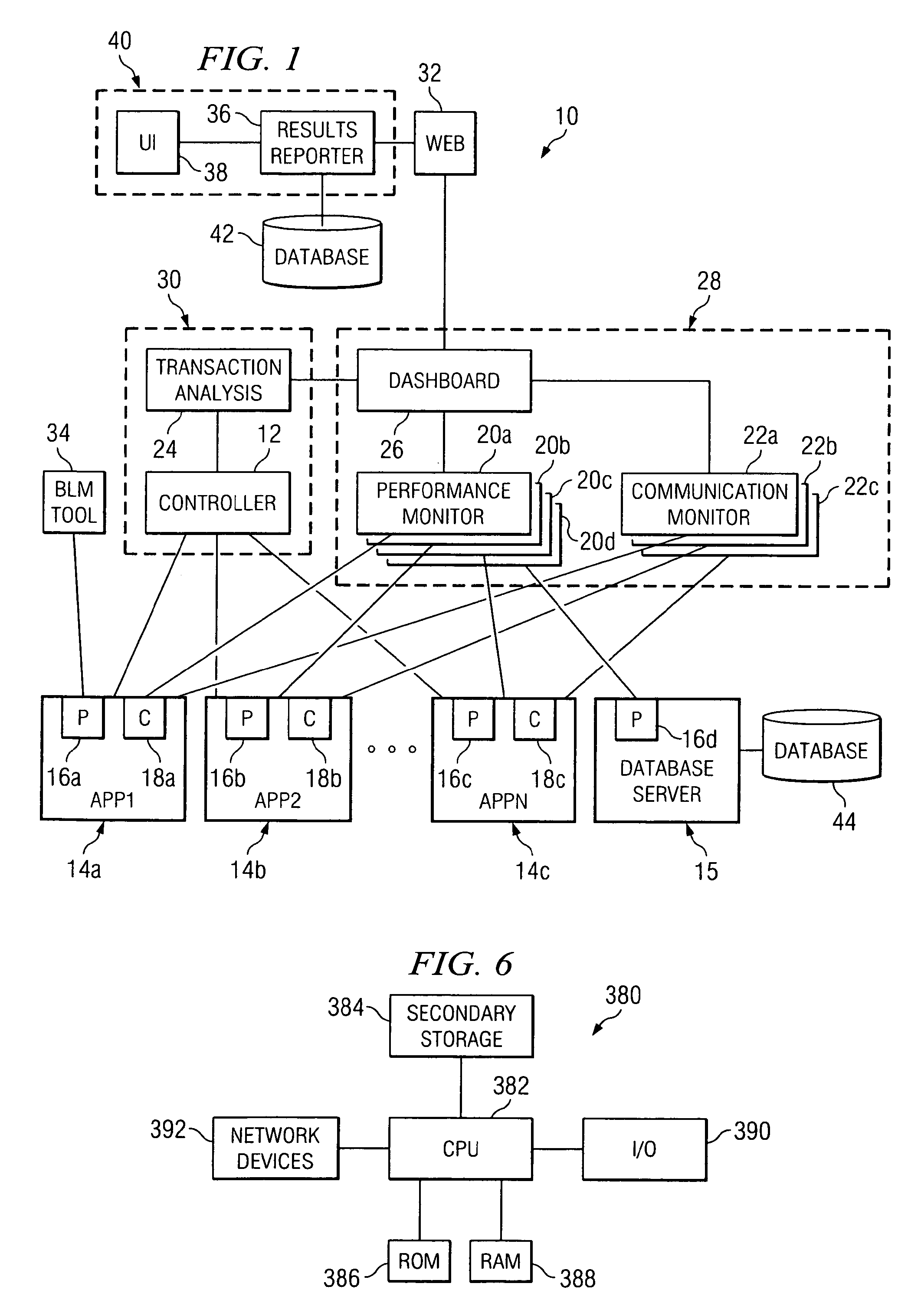
Load test monitoring system
a monitoring system and test technology, applied in the field of testing computer software, can solve problems such as system transaction throughput bogging down and infusing enterprise capital into computing resources
- Summary
- Abstract
- Description
- Claims
- Application Information
AI Technical Summary
Benefits of technology
Problems solved by technology
Method used
Image

Examples
Embodiment Construction
[0021]It should be understood at the outset that although an exemplary implementation of one embodiment of the present disclosure is illustrated below, the present system may be implemented using any number of techniques, whether currently known or in existence. The present disclosure should in no way be limited to the exemplary implementations, drawings, and techniques illustrated below, including the exemplary design and implementation illustrated and described herein.
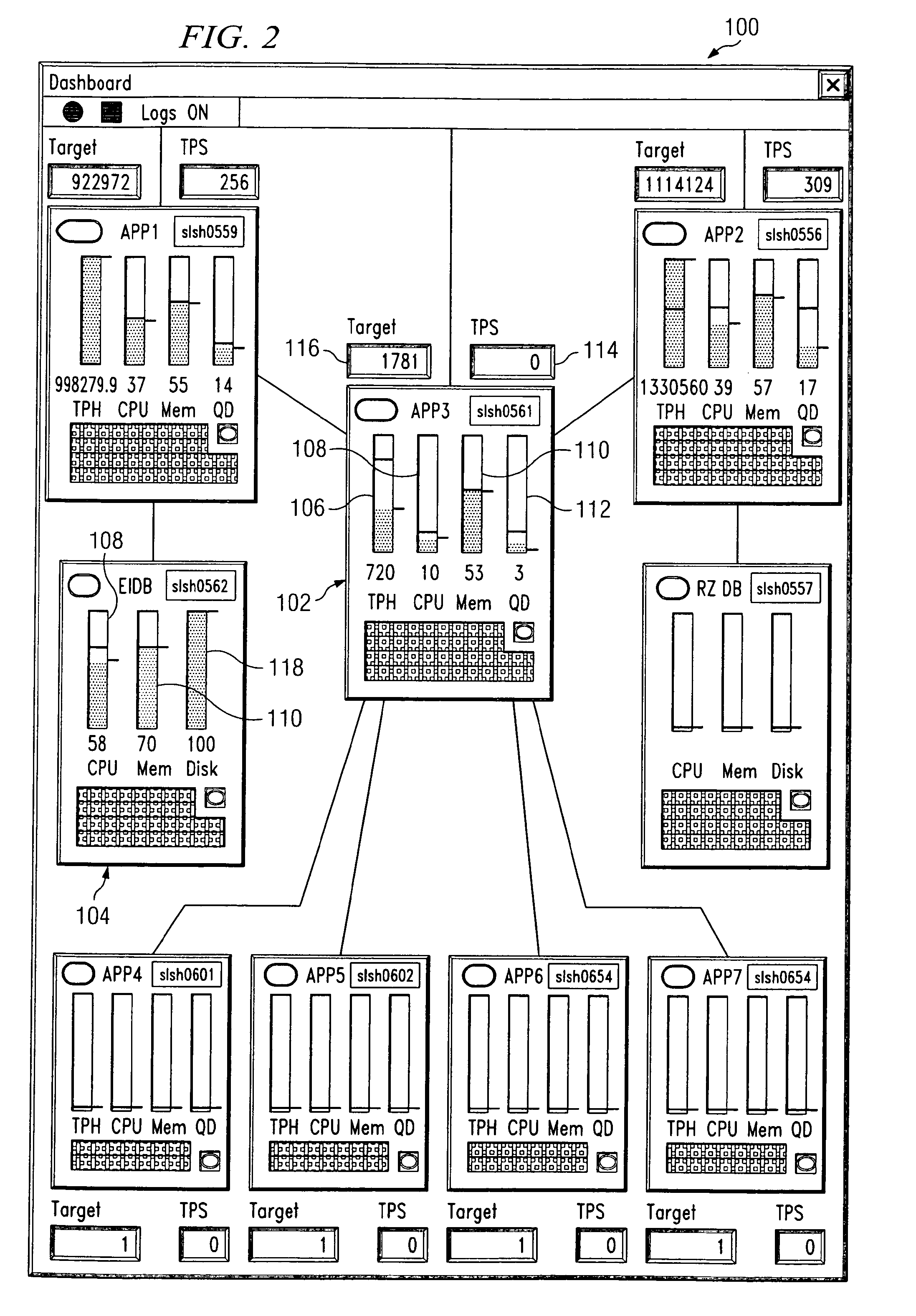
[0022]Confirming that a desirable volume of transactions or other processing is being imposed on a computer system during load testing may be difficult. In some computer systems multiple computers cooperate to provide the needed processing capacity, and during load testing each computer system must be loaded with a desirable volume of processing. It may be that a load test operator is focused on three primary application servers involved in load testing and monitors the load imposed on these three primary application...
PUM
 Abstract
Description
Claims
Application Information