Reciprocating pump having a ceramic piston

a ceramic piston and reciprocating pump technology, applied in the field of reciprocating pumps, can solve the problems of reducing the efficiency of the pump, wasting a fairly significant amount of material being pumped, and creating maintenance problems

Active Publication Date: 2006-11-14
COORSTEK INC
View PDF11 Cites 27 Cited by
  • Summary
  • Abstract
  • Description
  • Claims
  • Application Information

AI Technical Summary

Benefits of technology

[0014]The pump body can also be allowed to cool to the ambient temperature. This cooling can cause the pump body to contract, perhaps placing the ceramic plunger housing under compression. A ceramic plunger can be slidably disposed within the cylindrical bore of the plunger housing and the ceramic plunger can have an exterior diameter that is smaller than the interior diameter of the cylindrical bore. In certain aspects, allowing the pump body to cool to the ambient temperature can have the effect of forcing the internal diameter of the bore to contract to within a certain tolerance of the external diameter of the plunger.

Problems solved by technology

This leakage not only can reduce the efficiency of the pump, it can create maintenance issues and waste a fairly significant amount of the material being pumped.
Unfortunately, however, in order to adequately seal the plunger from leakage, such packing materials usually must maintain contact with the plunger as it moves reciprocally.
The packing materials, therefore, tend to degrade relatively quickly (due at least in part to friction between the plunger, the packing material and / or the fluids being pumped, as well as the expendable nature of the packing materials themselves), allowing progressively more leakage over time.
Moreover, as the packing materials degrade, there is a tendency by users to tighten the fitting on such pumps periodically as the packing materials degrade, compressing the packing materials to prevent this progressive leakage, which can significantly impact the efficiency of the pump and require more power for operation.
Furthermore, over time, the packing materials can, in fact, score the plunger itself, requiring replacement of the plunger, which can be costly and time consuming.
This problem, which can be mitigated, but generally not eliminated, by the use of lubricants to reduce friction, is exacerbated by the fact that such pumps often are used in relatively remote locations because of their desirability as being self-powered, such that they can run unattended for relatively long periods of time.
Moreover, the use of lubricants imposes additional maintenance overhead and expense, and it presents the danger that the lubricant might contaminate the material being pumped.

Method used


Image

  • Reciprocating pump having a ceramic piston
  • Reciprocating pump having a ceramic piston
  • Reciprocating pump having a ceramic piston

Examples


Embodiment Construction

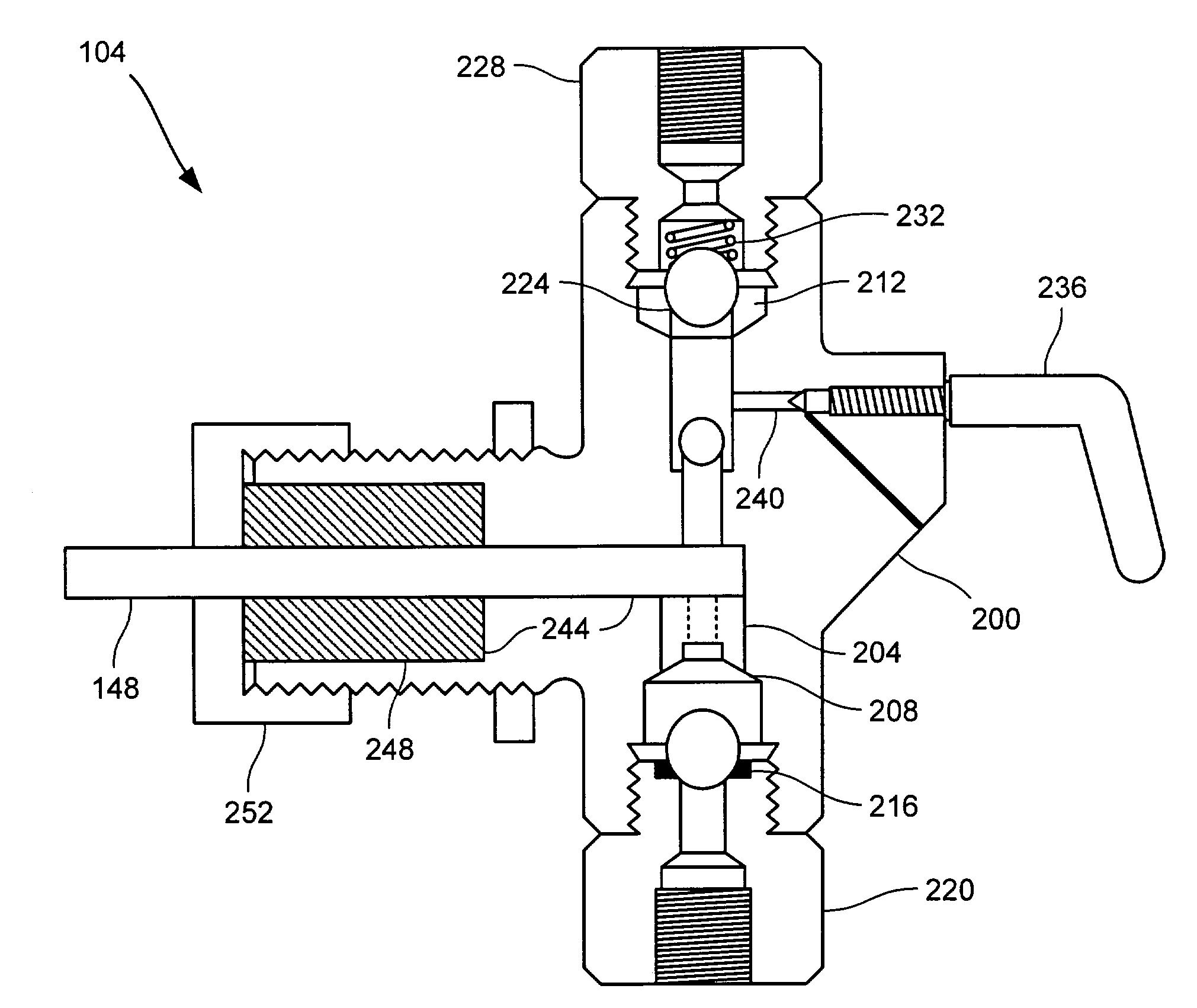
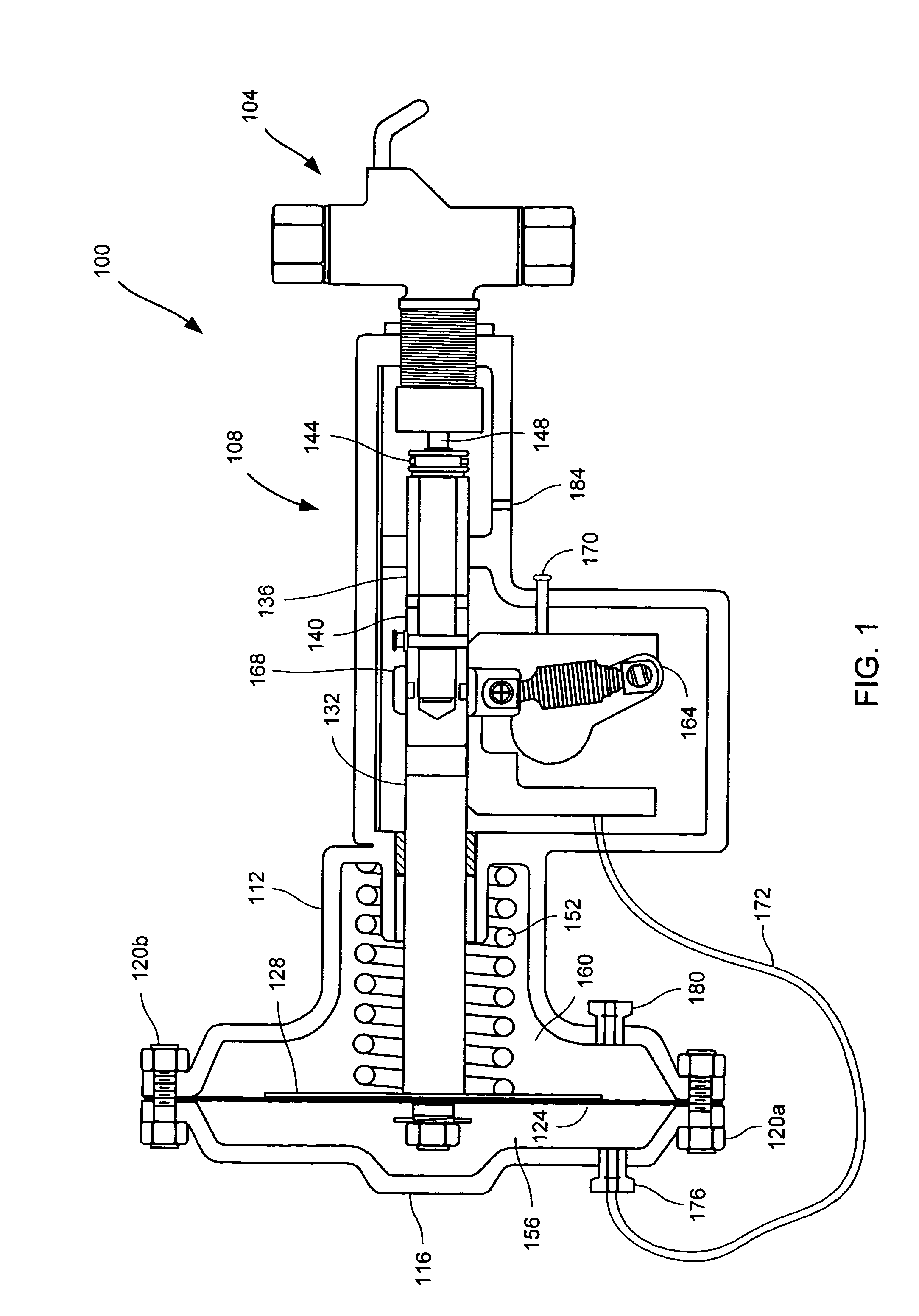
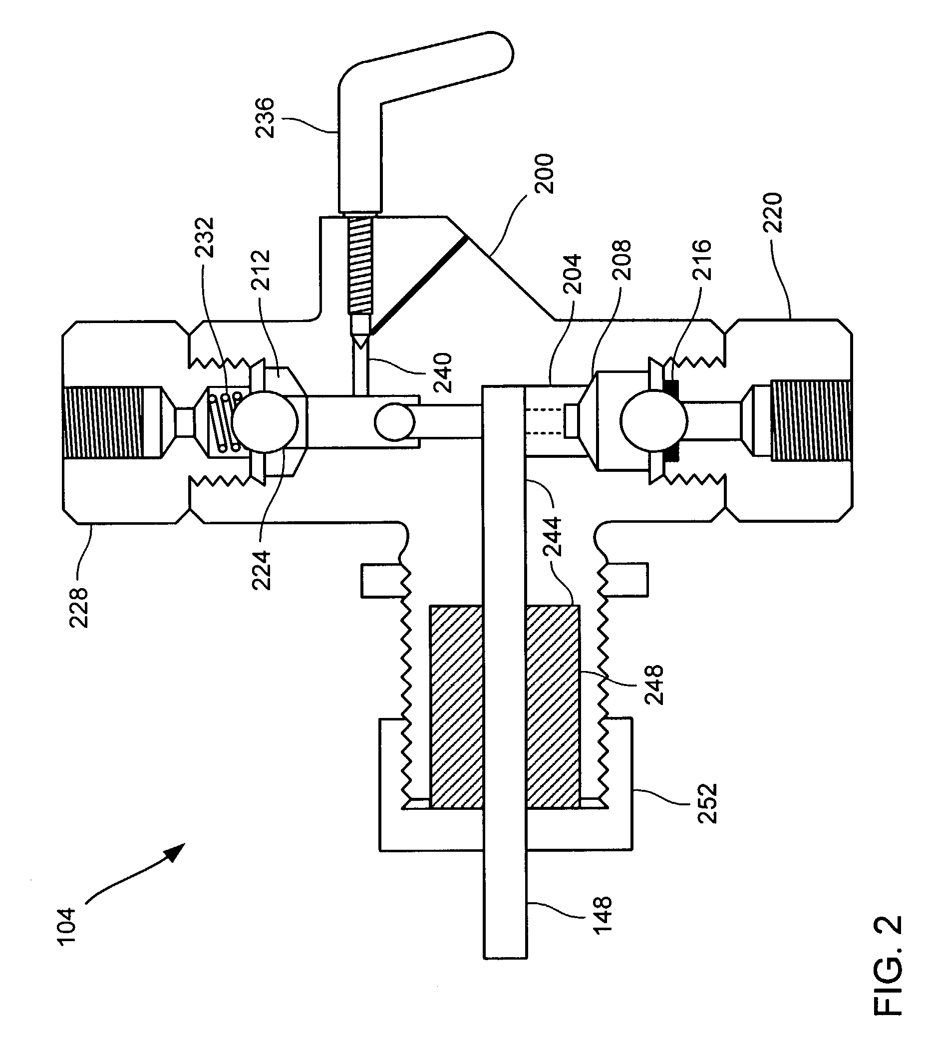
[0025]Among other things, embodiments of the invention provide plunger pumps, as well as methods for their production. In accordance with certain embodiments, a plunger pump can comprise a pump chamber and a ceramic plunger housing, as well as a ceramic plunger slidably disposed within a bore defined by the plunger housing. In a certain aspect, the outside diameter of the plunger can fit the inside diameter of the housing to within a certain tolerance, and the tolerance can operate to prevent the material being pumped from escaping from the pump chamber through the bore. In another aspect, for a plunger and housing exhibiting a certain tolerance, the length of the housing can be designed to control the rate of any leakage.

[0026]According to various embodiments of the invention, a ceramic plunger and housing can operate to allow essentially leak-proof pumping mechanism without the need for any packing materials, which, those skilled in the art will recognize, can tend to degrade over...


PUM


Abstract

Various embodiments of the invention, therefore, provide pumps, and methods for their production. One exemplary embodiment of the invention comprises a ceramic plunger pump assembly. The pump assembly can include a pump body, which defines a pump chamber with an inlet port and an outlet port. The pump body can further define a plunger port disposed between the inlet port and the outlet port. In certain embodiments, the pump assembly can further include a ceramic plunger housing, which defines a cylindrical bore having an interior diameter. The plunger housing can be disposed within the plunger port. The pump assembly can also include a ceramic plunger. In particular embodiments, the ceramic plunger is slidably disposed within the cylindrical bore, such that the ceramic plunger may be reciprocated back and forth within the bore. Thus, the fluid can be moved from the inlet port of the pump chamber to the outlet port of the pump chamber through the reciprocal action of the plunger.

Description

BACKGROUND OF THE INVENTION[0001]The present invention relates generally to pumps and methods of their construction.[0002]In the past, there has been a need for self-powered pumps which could be used without the presence of a separate power source (such as electricity) to perform certain tasks, including, for example, the injection of additives into gas lines, process tanks, and the like. A style of pump termed a “plunger pump” often has been used for such purposes. One such pump, described as a “fluid operated pump,” is detailed in U.S. Pat. No. 3,093,122, the entire disclosure of which is incorporated herein for all purposes.[0003]Those skilled in the art will ascertain that pumps generally, and plunger pumps in particular, depend on effective sealing members in order to avoid leakage of the material to be pumped. Without proper sealing, the material being pumped can tend to evacuate the pump chamber along the length of the plunger, instead of through the designed exit port. This ...

Claims


Application Information

Patent Timeline
Patent Type & Authority Patents(United States)
IPC IPC(8): F04B53/10F04B15/08F04B53/14
CPCF04B15/08F04B53/14F05C2203/08Y10S417/01
Inventor CHENOWETH, J. MARK
Owner COORSTEK INC
Why Eureka
Try Eureka