Demonstration system of electronic equipment and demonstration method for electronic equipment

a technology of demonstration system and electronic equipment, applied in the direction of data recording, record carrier construction details, education models, etc., can solve the problems of limited area, complicated operation, and increased operation functions, and achieve the effect of quick and precise understanding of functions

Inactive Publication Date: 2006-11-14
PIONEER CORP
View PDF17 Cites 15 Cited by
  • Summary
  • Abstract
  • Description
  • Claims
  • Application Information

AI Technical Summary

Benefits of technology

[0012]Accordingly, when a user operates the demonstration operation part, the user can see the display demonstration for successively displaying information of the electronic equipment on the display part. In addition to that, the user can see the movable section demonstration to demonstrate an actual movement of the operation unit. Therefore, it is possible for the user to quickly, positively understand the functions provided in the electronic equipment.
[0014]According to this embodiment, it is possible to continuously conduct a demonstration regarding the display and a demonstration regarding the movable section under the condition. The demonstration regarding the display and the demonstration regarding the movable section may be alternately conducted for each function. In this way, the user can continuously see the demonstration conducted by the display part and the demonstration conducted by the movable section. Therefore, functions of the electronic equipment can be easily understood.
[0028]According to this embodiment, it is unnecessary to provide an exclusive demonstration control part in the operation unit, and it becomes possible to start a demonstration by simultaneously operate several means for operating the electronic equipment. In this way, an operation face of the operation unit, area of which is limited, is effectively used.
[0035]Since the user can continuously observe the display demonstration and the movable section demonstration, it is possible for the user to quickly, precisely understand the functions of the electronic equipment.

Problems solved by technology

In these car audio apparatus, operation functions tend to increase and the operation tends to become complicated, and many operation functions need be attached on an instrument panel, the area of which is limited.
However, in the system in which a plurality of operation units are provided as described above and further those operation units are movable, it is difficult to make a user understand the functions of the electronic equipment sufficiently by using a display section for explaining the functions.
Further, it is difficult to make the user understand how the movable operation units are operated.

Method used


Image

  • Demonstration system of electronic equipment and demonstration method for electronic equipment
  • Demonstration system of electronic equipment and demonstration method for electronic equipment
  • Demonstration system of electronic equipment and demonstration method for electronic equipment

Examples


Embodiment Construction

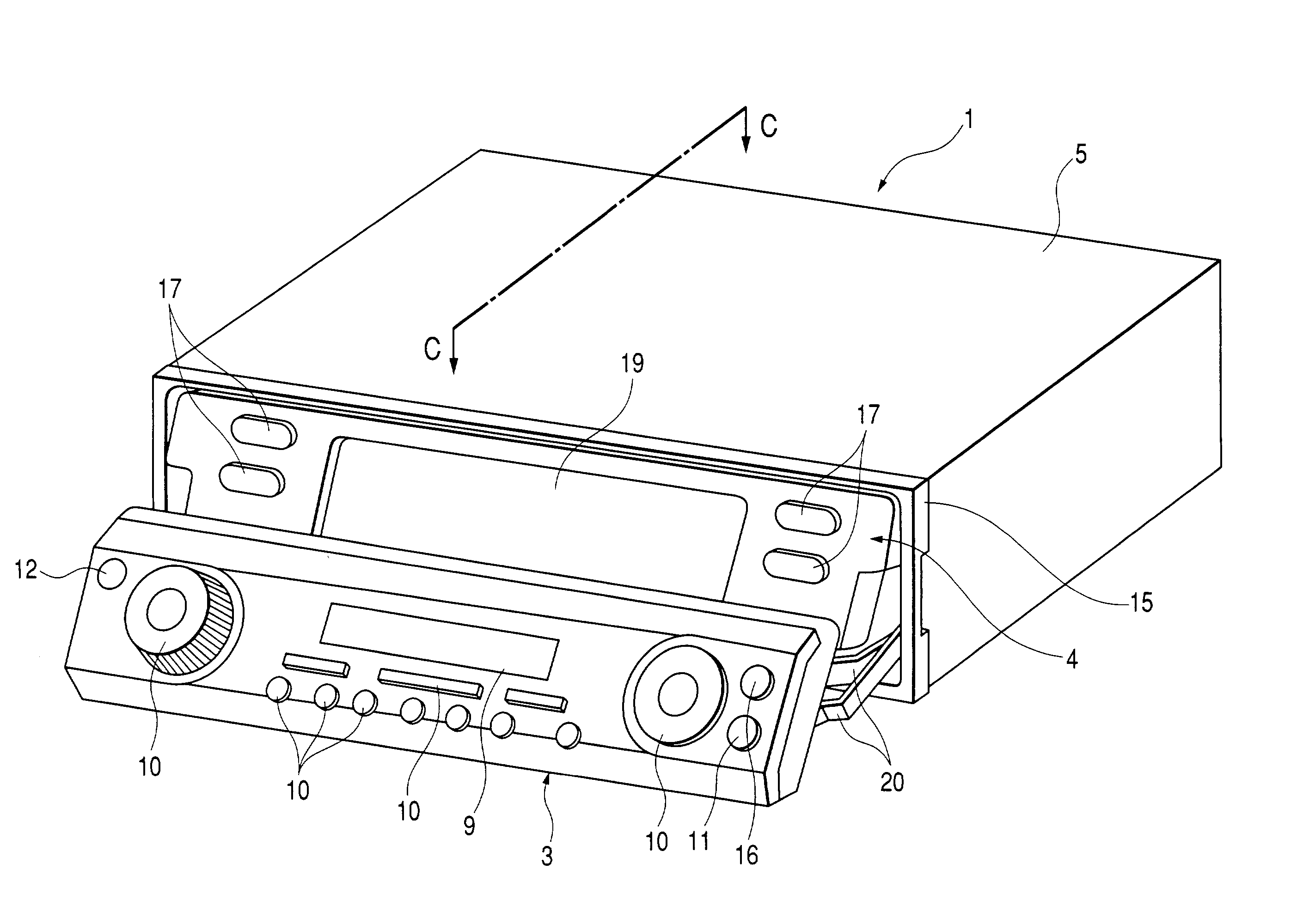
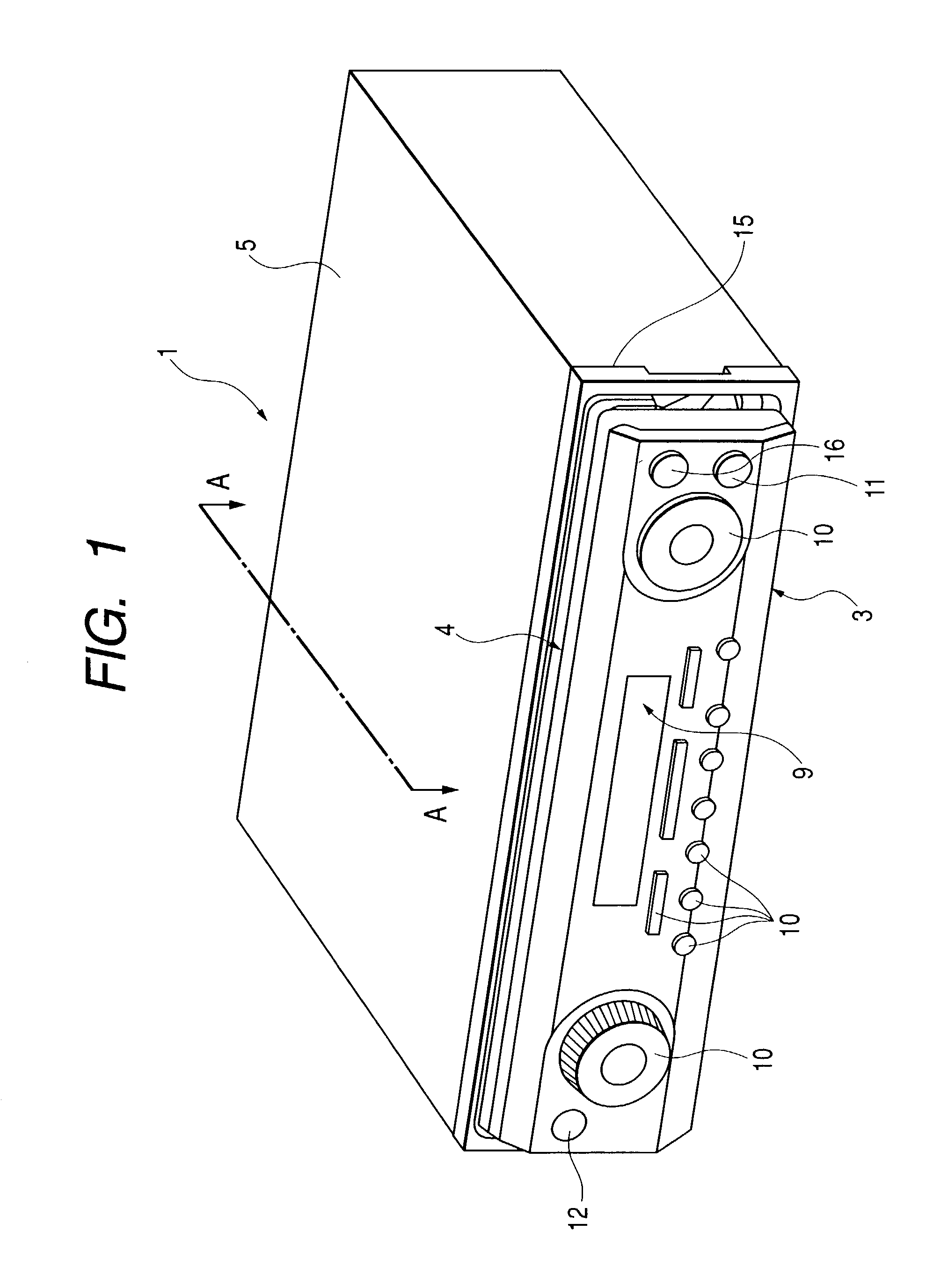
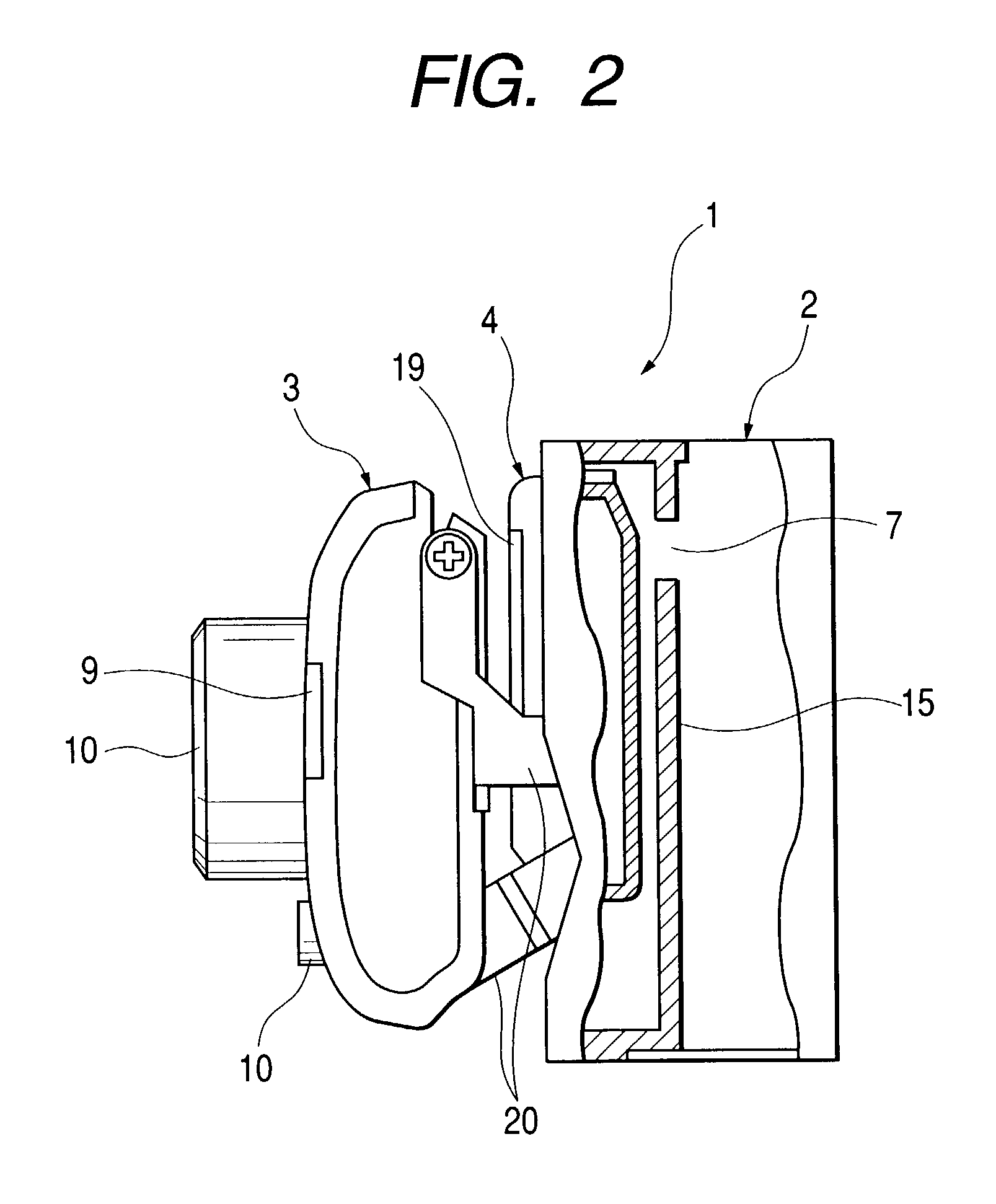
[0048]First, referring to FIGS. 1 to 7, explanations will be made into the constitution of an electronic equipment applied to an electronic equipment demonstration system of the present invention. FIGS. 1 and 2 are views showing the constitution of an electronic equipment used for the electronic equipment demonstration system of the present invention. FIGS. 3 and 4 are views showing a first operation state of the electronic equipment. FIGS. 5 and 6 are views showing a second operation state of the electronic equipment. FIG. 7 is a schematic illustration for explaining a drive mechanism of an operation panel of the electronic equipment.

[0049]As shown in FIG. 1, in the electronic equipment 1, there are provided two operation units for operating the electronic equipment 1 which are arranged in a front panel section 15 of the electronic equipment 1 being superposed in a back and forth direction. One operation unit arranged at the front side is a first operation unit 3, and the other ope...


PUM

PropertyMeasurementUnit
movementaaaaaaaaaa
areaaaaaaaaaaa
Organicaaaaaaaaaa

Abstract

A demonstration system of an electronic equipment. The electronic equipment includes first and second operation units which are arranged on a front panel of the electronic equipment. In the first operation unit, there are provided display device, various operation keys, demonstration key, light receiving part, and opening / closing key. In the second operation unit, there are provided an operation key and a display device. The demonstration key is an input key for giving a command to start a demonstration of the electronic equipment. A display demonstration, in which the display devices are used, and a movable section demonstration, in which the first and the second operation unit are operated, are continuously conducted.

Description

[0001]The present disclosure relates to the subject matter contained in Japanese Patent Application No. 2001-382692 filed Dec. 17, 2001, which is incorporated herein by reference in its entirety.BACKGROUND OF THE INVENTION[0002]1. Field of the Invention[0003]The present invention relates to a demonstration system and method of an electronic equipment attached to a moving body such as a vehicle, wherein a plurality of movable operation units are arranged on a front panel of the electronic equipment.[0004]2. Description of the Related Art[0005]Conventionally, various car audio apparatus such as a CD (Compact Disc) player, a DVD player, an MD (Mini Disc) player and an AM / FM tuner mounted in an instrument panel of a vehicle, and a car audio apparatus in which these are combined integrally or in which these are integrated with a navigation apparatus are used as electronic equipments. Also, there is a type having means for operating the electronic equipment by remote control.[0006]In thes...

Claims


Application Information

Patent Timeline
Patent Type & Authority Patents(United States)
IPC IPC(8): G09B11/00G11B33/02H04B1/08H04B1/16
CPCG11B33/027H04B1/082H04B1/1646
Inventor MATUMOTO, ISAOKOBAYASHI, HIRONORINISHIDA, NORIFUMIFUKUYA, MAKOTOSHIBATA, NAOYANATORI, TETSUYAMAEDA, KOUJI
Owner PIONEER CORP
Why Eureka
Try Eureka