Separable insulated connector and method

a technology of separable insulated connectors and connectors, which is applied in the direction of electrically conductive connections, coupling device connections, high-tension/heavy-dress switches, etc., can solve the problems of gas dissipation flashover, operator drag the electrical arc out of the bushing, and the possibility of flashover

Active Publication Date: 2006-11-14
EATON INTELLIGENT POWER LTD
View PDF13 Cites 32 Cited by
  • Summary
  • Abstract
  • Description
  • Claims
  • Application Information

AI Technical Summary

Problems solved by technology

Since one or both connectors are energized during loadbreak, there exists a possibility of a flashover occurring.
A flashover occurs when the electrical arc generated by an energized connector extends to a nearby ground point, which is undesirable.
Particularly, for example, when a line-crew operator separates the male and female connectors in a loadbreak operation too slowly, the operator can drag the electrical arc out of the bushing.
During a switching operation, flashover may be caused at least in part by air pressure and conductive particles that build up within the electrical connectors.
Since the fragments of copper and carbon are conductive, they can easily form a conductive path, resulting in a flashover induced by the gas dissipation.

Method used


Image

  • Separable insulated connector and method
  • Separable insulated connector and method
  • Separable insulated connector and method

Examples


Embodiment Construction

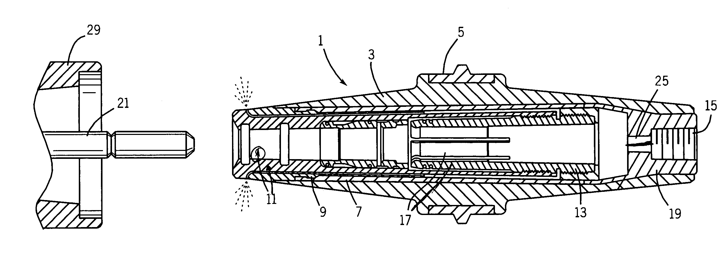
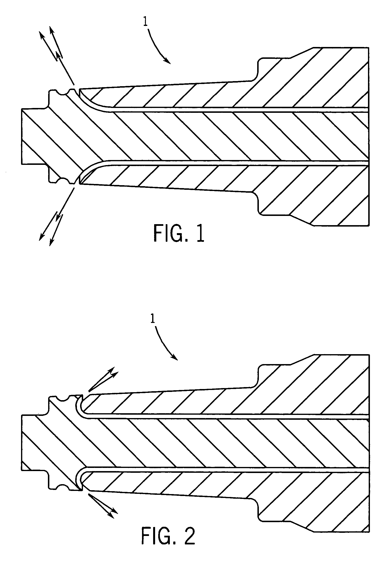
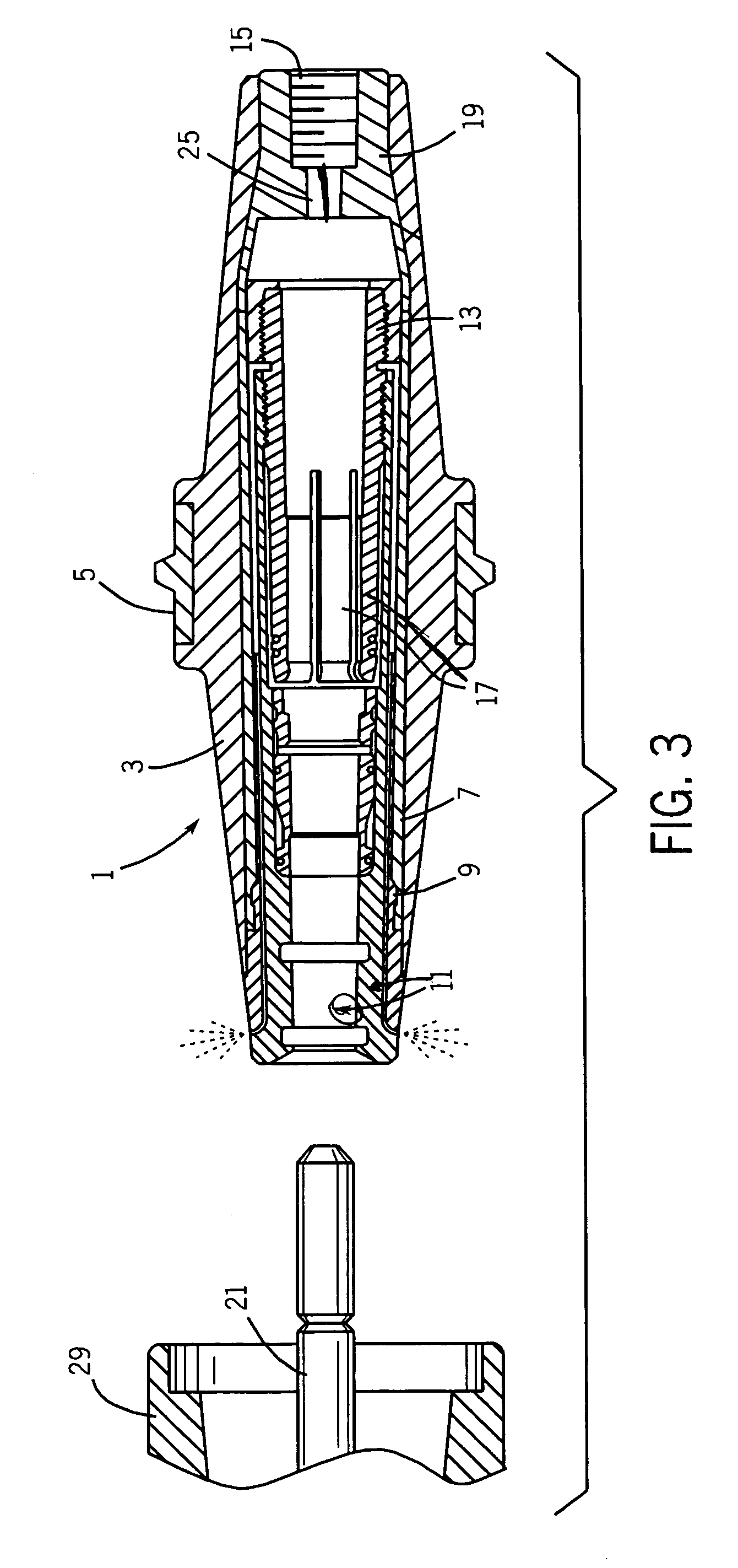
[0014]Referring to FIG. 1, a general layout of a venting path within bushing 1 is illustrated. The venting path diverts the flow of gases and particles at angle between ten degrees (10°) and ninety degrees (90°), relative to the initial direction of the gas flow. As gases and particles are generated during loadbreak switching, the matter travels through a venting path formed in the body of the bushing 1. The matter flows through the venting path in the general direction as the axis of motion of a mating connector. Upon reaching the terminal portion of the venting path, the venting path curves at an angle that allows the matter to exit bushing 1 and be redirected away in a non-parallel direction, which may be between ten degrees (10°) and ninety degrees (90°), relative to the initial direction of the gas flow. The venting path illustrated in FIG. 1 also may redirect the matter away from other energized apparatuses or ground planes. The venting path shown in FIGS. 1, 2, and 3 may be f...


PUM


Abstract

A separable insulated connector provides a current path for high-energy distribution between a power transmission or power distribution apparatus and an elbow connector. As gases and conductive particles exit the separable insulated connector during loadbreak switching, the gases and particles are re-directed away from a mating electrode probe and diverted along a path non-parallel to the electrode probe.

Description

BACKGROUND[0001]The present invention relates generally to the field of loadbreak switching. More particularly, this invention relates to enhancements in separable insulated connectors for reducing the probability of flashover during loadbreak switching.RELATED ART[0002]Separable insulated connectors provide the interconnection between energy sources and energy distribution systems. Typically, energy distribution is made possible through a large power distribution system, which results in power distribution to homes, businesses, and industrial settings throughout a particular region. In most cases, the distribution of power begins at a power generation facility, such as a power plant. As the power leaves the power plant, it enters a transmission substation to be converted up to extremely high voltages for long-distance transmission, typically in the range of 150 kV to 750 kV. Then, power is transmitted over high-voltage transmission lines and is later converted down to distribution ...

Claims


Application Information

Patent Timeline
Patent Type & Authority Patents(United States)
IPC IPC(8): H01R13/53
CPCH01R13/53H01H33/7023H01R13/637H01R24/20H01R2101/00
Inventor HUGHES, DAVID C.ROSCIZEWSKI, PAUL M.
Owner EATON INTELLIGENT POWER LTD
Why Eureka
Try Eureka