Compression bone screw device

a bone screw and compression technology, applied in the field of orthopaedic surgical devices, can solve the problems of affecting the effect of compression force, affecting the effect of compression force,

Inactive Publication Date: 2006-11-14
WATKINS WILLIAM T +1
View PDF26 Cites 78 Cited by
  • Summary
  • Abstract
  • Description
  • Claims
  • Application Information

AI Technical Summary

Problems solved by technology

The prior art devices and methods suffer from several disadvantages in installation, adjustability and short and long-term effectiveness.
Prior art lag screw and adjoining compression screws may provide sufficient initial compression forces across the bone, but suffer the significant disadvantage of losing compressive force capability and effectiveness over a very short period of time through common bone resorption or actual shrinkage of the bone across the fracture during the initial phases of the bone healing process.
Prior art side plates and integral, fixed barrels suffer from disadvantages of requiring a long incision to accommodate the long, downstanding side plate along the femoral shaft and the angular oriented barrel 26 is fixed in the anterior, posterior, medial and lateral planes.
This can result in improper alignment of the lag screw in the side plate barrel which, over time, can loosen, cause cut-out of the lag screw in the femoral head, bind the lag screw in the barrel or cause improper transfer of load on the device.

Method used


Image

  • Compression bone screw device
  • Compression bone screw device
  • Compression bone screw device

Examples


Embodiment Construction

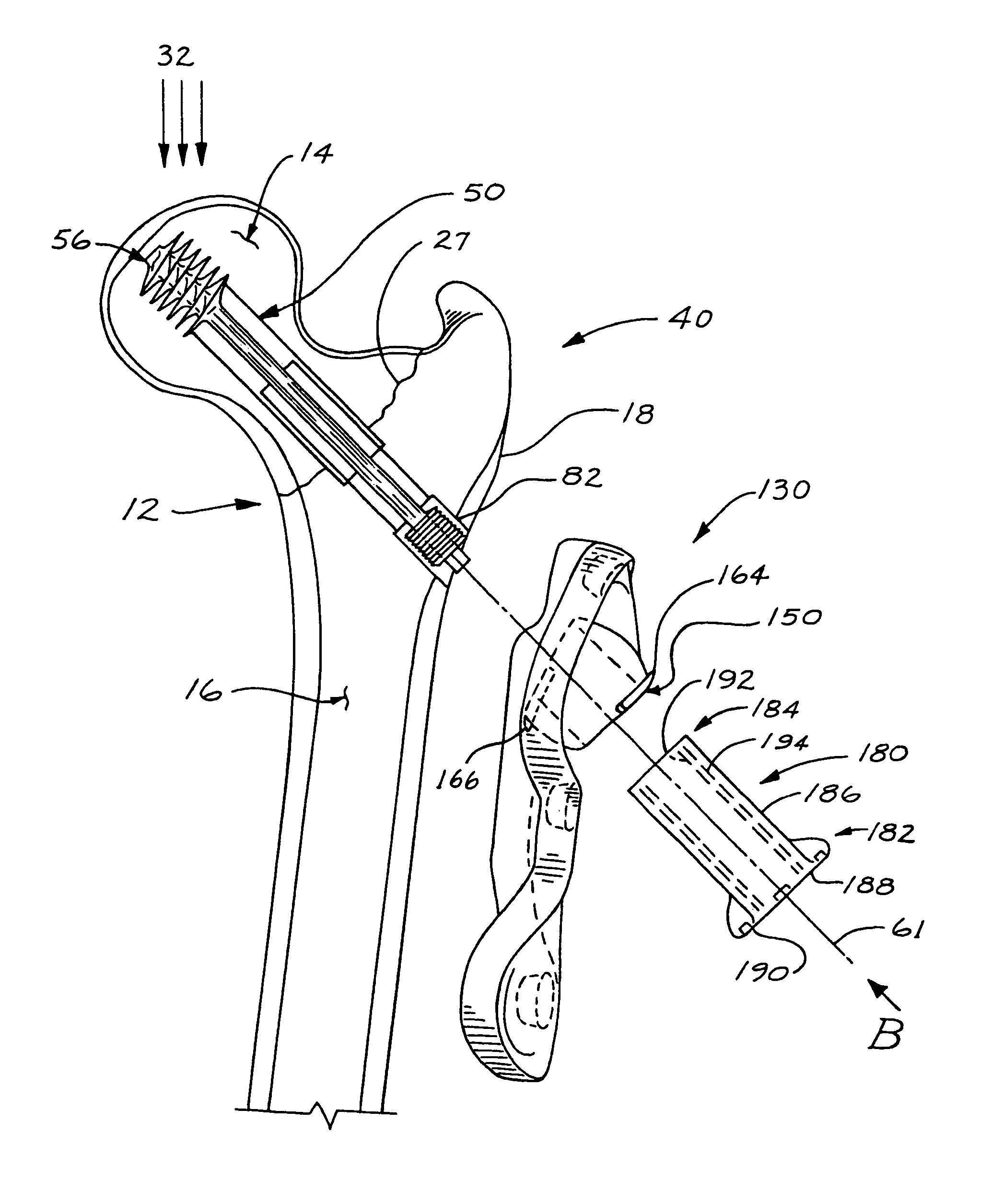
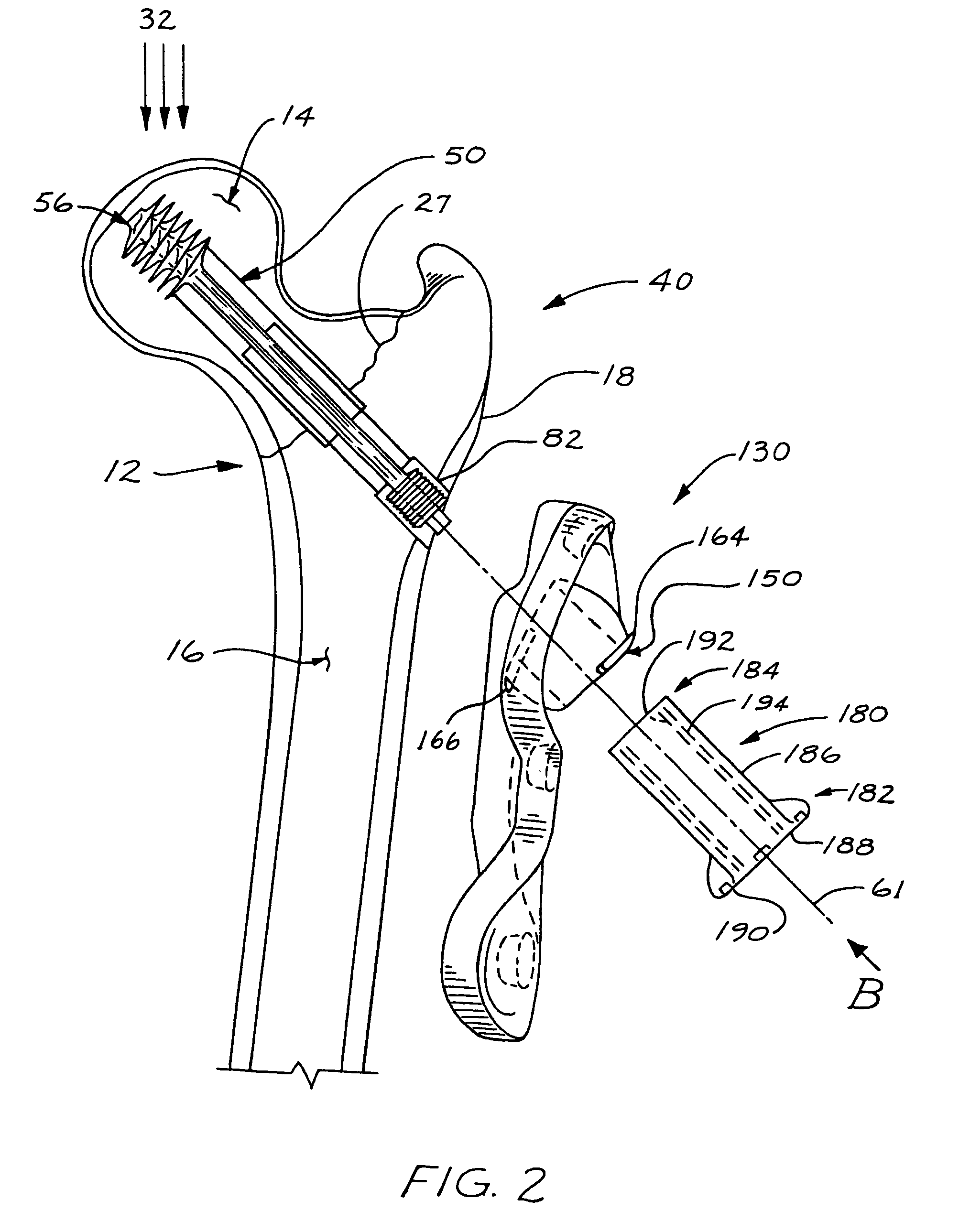
[0029]Referring to FIGS. 2–13, the preferred embodiment of a compression bone screw device is illustrated. Referring to FIG. 2, a preferred, but not exclusive application of the present invention is to repair a fracture 27 in a human femur 12 having a femoral head 14 and a femoral shaft 16. The aspect illustrated includes a constant compression lag screw 50, a side plate 130 with a rollerball 150 and compression barrel 180. It is understood that the present invention is usable in other applications other than as a compression hip screw as explained below.

[0030]Referring to FIGS. 2–4, a constant compression lag screw 50 is illustrated. Referring to FIGS. 3 and 4, a constant compression lag screw 50 includes an outer member 52 having a first end 54 with coarse threads 56. Threads 56 may vary in thread size and pitch and are suitable for threading and secure engagement of the lag screw in the femoral head as shown in FIG. 2 or to suit the particular application. Lag screw outer member ...


PUM


Abstract

A compression bone screw device for fixating a fractured bone. The device includes a constant compression lag screw, a side plate having a moveable rollerball for receipt of the lag screw and a compression member engageable with the lag screw and rollerball to impart a constant compressive force across the bone fracture.

Description

CROSS-REFERENCE TO RELATED APPLICATIONS[0001]This application claims benefit of the provisional patent application Ser. No. 60 / 485,329 filed Jul. 7, 2003 entitled Minimally Invasive Compression Hip Screw System. This claim is made under 35 U.S.C. § 119(e) and C.F.R. § 1.53(c)(3).FIELD OF THE INVENTION[0002]The present invention relates to orthopaedic surgical devices used to join and promote healing of fractured bone, and more particularly, and not by limitation, devices used to fixate proximal femoral fractures.BACKGROUND OF THE INVENTION[0003]Compression hip and bone screw devices for use in fixating a fractured bone during the healing process have been used for years. Referring to FIG. 1, the typical device 10 used for hip fractures uses a lag screw 22 that is inserted into a femur 12 and used with a fixed side plate 24 which is attached to the femoral shaft 16. The lag screw is secured in the femoral head 14 on one end and abuttingly engages the barrel on the other end using a c...

Claims


Application Information

Patent Timeline
Patent Type & Authority Patents(United States)
IPC IPC(8): A61B17/58A61B17/74
CPCA61B17/746A61B17/748
Inventor WATKINS, WILLIAM T.WADE, GARY
Owner WATKINS WILLIAM T
Why Eureka
Try Eureka