Femoral compression device with support

a technology of femoral compression and support, which is applied in the field of femoral compression devices, can solve problems such as unnecessary bleeding

Inactive Publication Date: 2006-11-14
ST JUDE MEDICAL COORDINATION CENT
View PDF10 Cites 60 Cited by
  • Summary
  • Abstract
  • Description
  • Claims
  • Application Information

AI Technical Summary

Benefits of technology

[0003]Because of the position of the femoral artery, i.e. at one of the patient's groins and not in the centre of the body, the two extensions have different lengths. This means that the moment arm from the end of the first extension to the centre of the inflatable air cushion differs from the corresponding moment arm of the second extension. In other words, this prior art femoral compression device exhibits an inherent imbalance, which strives to tilt the compression device and which can make the inflatable air cushion move away from the puncture site, thereby causing unnecessary bleeding.
[0004]An object of the present invention is therefore to provide an improved femoral compression device which during use presses against the femoral artery of a patient without showin

Problems solved by technology

In other words, this prior art femoral compression device exhibits an inherent imbalance, which strives to tilt the compressio

Method used


Image

  • Femoral compression device with support
  • Femoral compression device with support

Examples


Embodiment Construction

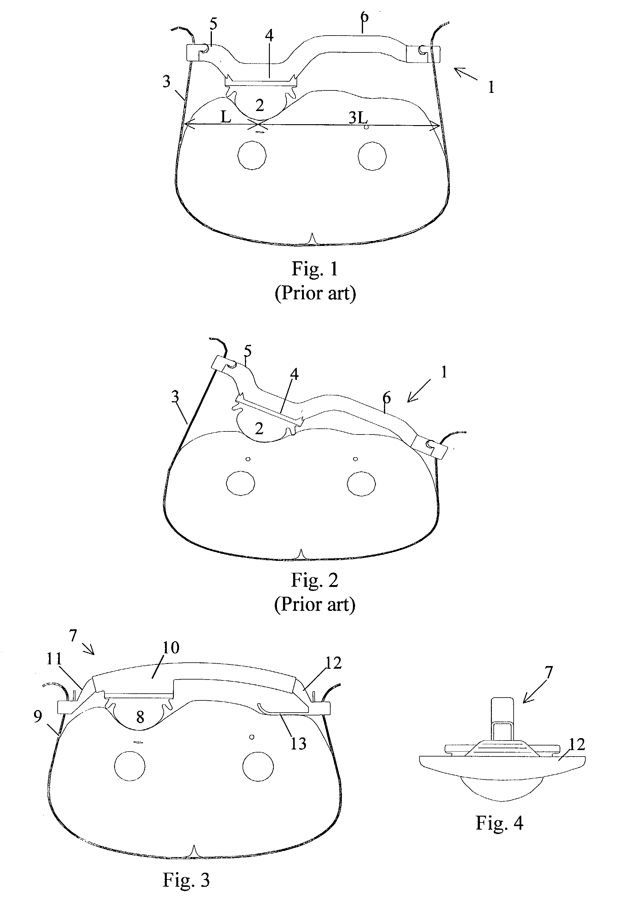
[0010]A prior art femoral compression device 1 is illustrated in cross-section in FIG. 1, where the compression device 1 is attached to the body of a patient. The compression device 1 comprises basically an inflatable air cushion 2, a belt 3, and base plate 4 provided with two extensions 5 and 6, which extend in opposite directions. In use, the belt 3 extends around the patient's body and is attached to the ends of the two extensions 5, 6. As can be seen from the figure, the first extension 5 is shorter than the second extension 6, which is due to the off-centre position of the femoral artery on which the air cushion 2 is intended to press.

[0011]In the exemplifying embodiment illustrated in FIG. 1, the distance from the end of the first extension 5 to the centre of the air cushion 2 is L, while the length from the end of the second extension 6 to the centre of the air cushion 2 is 3L. When the femoral compression device 1 is in its correct horizontal position, as shown in the figure...


PUM


Abstract

A femoral compression device includes a pressure applying device for compressive bearing at a puncture site at a femoral artery of a patient and for applying pressure on the puncture site, a belt adapted to be fixed around the patient's body, and a base plate provided with first and second extensions, with the end of the first extension being closer to the pressure applying device than the end of the second extension and being provided with a fastener in the ends thereof for fastening of an end of the belt. The compression device also includes a support plate, which is attached to the second extension and which is adapted to bear against the patient's body, thereby compensating for the imbalance, which originates from the different extents of the two extensions, that otherwise would be present.

Description

BACKGROUND[0001]The present invention relates generally to a femoral compression device comprising a pressurizing (or pressure applying) means that presses against the femoral artery, and in particular to a femoral compression device comprising two extensions with different lengths and an extra support that in use compensates for the imbalance of the device.[0002]The present invention is an improvement of the femoral compression device disclosed in the patents U.S. Pat. No. 5,307,811 and EP 0 462 088, which are assigned to the present assignee and which claim priority from SE 9002077 and SE 9003271. All four of these documents are incorporated herein by reference in their entirety. A femoral compression device according to these publications comprises basically a pressurizing means for compressive bearing against a puncture site at a femoral artery of a patient, a belt adapted to be fixed around the patient's body, and a base plate supporting the pressurizing means and being provide...

Claims


Application Information

Patent Timeline
IPC IPC(8): A61F5/34A61B17/00A61B17/12A61B17/132A61B17/135
CPCA61B17/1325A61B17/135A61B2017/00557
Inventor ANG.KERFELDT, DAN
Owner ST JUDE MEDICAL COORDINATION CENT
Why Eureka
Try Eureka