Method for producing a constraint-satisfied cam acceleration profile

a technology of acceleration profile and cam, which is applied in the direction of valve drives, machines/engines, instruments, etc., can solve the problems of inability to meet the constraints of valve motion in the initial profile without adjusting the initial profile, failure to achieve the known approach, and inability to deliver a highly precise solution

Active Publication Date: 2006-11-14
FCA US
View PDF3 Cites 5 Cited by
  • Summary
  • Abstract
  • Description
  • Claims
  • Application Information

AI Technical Summary

Problems solved by technology

Additionally, manufacturing constraints such as the smallest radius of curvature that can be ground with a specific grinding wheel play a roll in the design process.
Unless a design engineer is extremely lucky, the initially selected acceleration profile for the cam will not meet all of a plurality of valve motion constraints without adjusting the initial profile.
There are problems with this known approach.
First, sometimes the known approach does not succeed or it does not deliver a highly precise solution.
Secondly, this known optimization approach is more computationally expensive than can be tolerated during interactive design within many popular computing environments (e. g., Matlab / Simulink).

Method used


Image

  • Method for producing a constraint-satisfied cam acceleration profile
  • Method for producing a constraint-satisfied cam acceleration profile
  • Method for producing a constraint-satisfied cam acceleration profile

Examples


Embodiment Construction

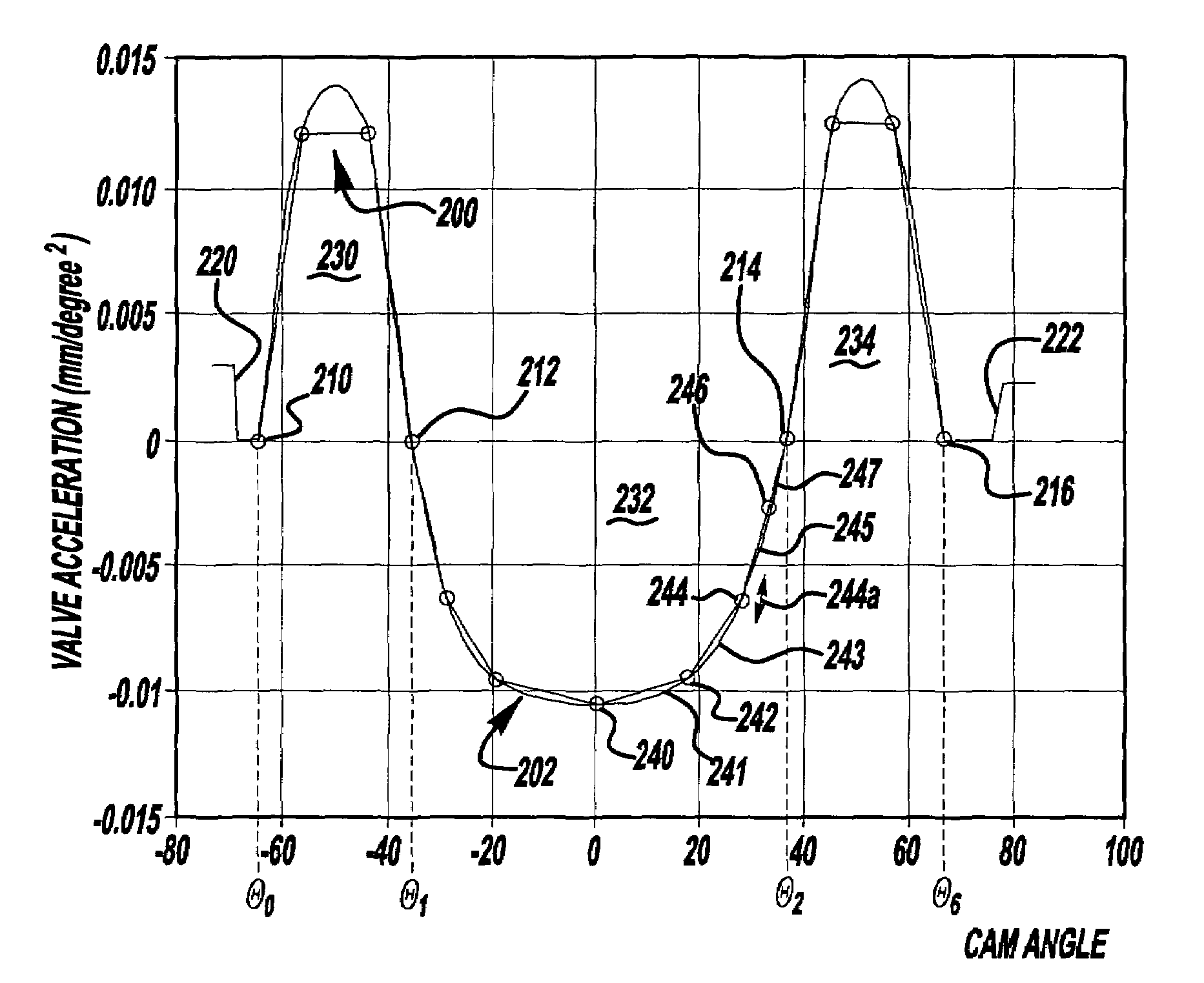
[0017]Suppose I(θ) defines valve lift as a function of the rotation angle θ of the cam producing that lift. The second derivative of I with respect to θ is commonly referred to as the valve acceleration profile a(θ).

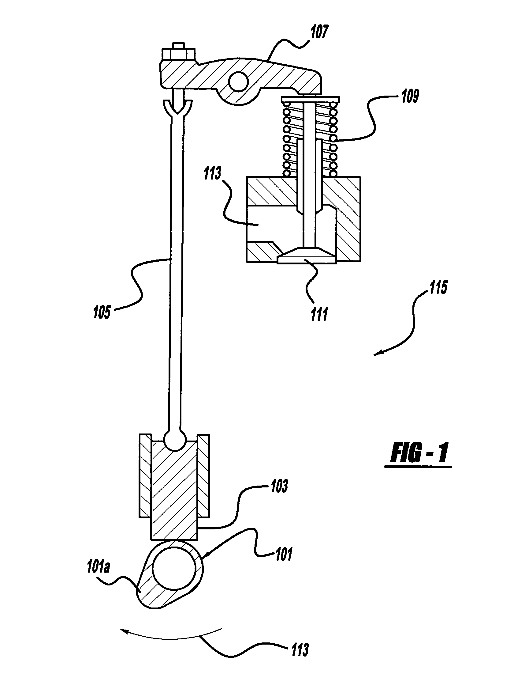
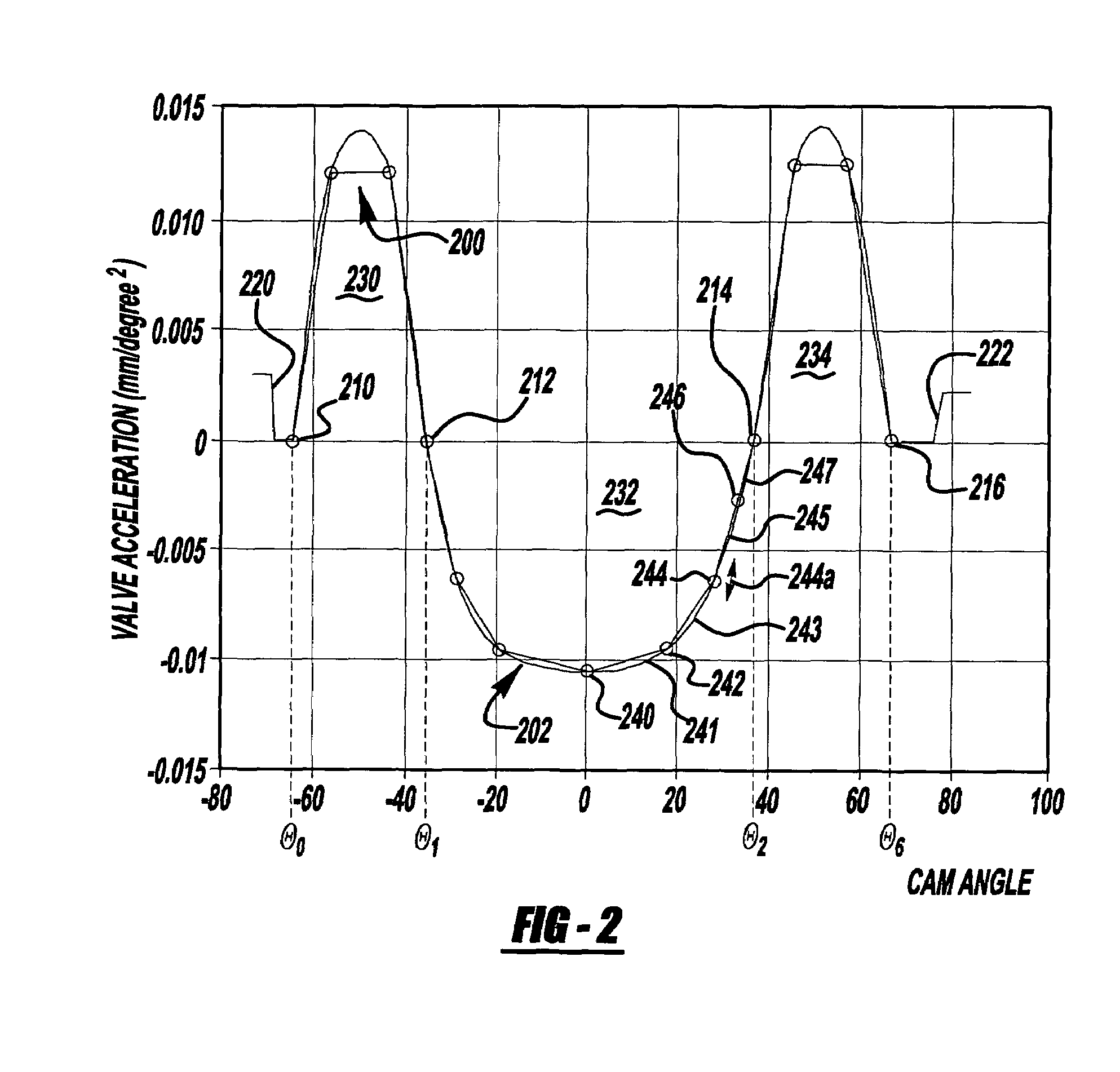
[0018]FIG. 2 shows an example valve acceleration profile for a cam, such as cam 101 of FIG. 1. The horizontal axis indicates cam angle. Cam angle zero corresponds to maximum lift—i.e., the angle where the nose of a cam lobe 101a contacts the follower 103. Negative angles correspond to valve motion induced by the opening side of the cam lobe and positive angles indicate motion induced by the closing side of that lobe.

[0019]The square waves 220 and 222 on the left and on the right of FIG. 2 are respectively called the opening and closing ramps of the acceleration profile. Acceleration is zero from angle −180° to the beginning of the opening ramp, and from the end of the closing ramp to +180° . Between the two ramps lies a typical valve acceleration curve, often called an a...


PUM


Abstract

A method for generating an acceleration profile for a valve operating cam of an internal combustion engine varies an adjustment point of an initial draft acceleration profile curve such that a determinant of a set of equations defining valve motion constraints and scaling factors is forced to zero. The equations may then be solved for values of the scaling factors which are applied to the initial draft acceleration profile curve to generate a desired profile which satisfies valve motion constraints.

Description

BACKGROUND OF THE INVENTION[0001]1. Field of the Invention[0002]The invention relates generally to methods for designing the profile of a cam for actuating a valve mechanism. More specifically, the invention relates to generation of an acceleration profile for a valve operating cam of an internal combustion engine, the profile satisfying a plurality of valve motion constraints.[0003]2. Discussion of the Prior Art[0004]Internal combustion engines use a well-known cam shaft system with a plurality of cams for opening and closing various valves associated with individual combustion cylinders of the engine. A conventional cam-actuated engine valve arrangement is shown in FIG. 1. Cam 101 rotates in the direction shown by arrow 113 so as to move cam follower or tappet 103 and push rod 105 against rocker arm 107 which, in turn, causes motion of spring biased valve 111 in an opening or closing direction for controlling communication with cylinder volume 115 with an input or output conduit 1...

Claims


Application Information

Patent Timeline
Patent Type & Authority Patents(United States)
IPC IPC(8): G06F17/10G06F17/50F01L1/08
CPCF01L1/08
Inventor MOSIER, RONALD G.GEIST, BRUCERESH, WILLIAM F
Owner FCA US
Why Eureka
Try Eureka