Measuring arrangement to determine location of corners for a building foundation and a wooden base frame, and the use thereof

a technology of measuring arrangement and building foundation, which is applied in the direction of active open surveying means, surveying instruments, instruments, etc., can solve the problem of one worker performing the process, and achieve the effect of improving accuracy and efficiency and effectively using a single worker

Inactive Publication Date: 2006-11-21
ARMSTRONG TIMOTHY D +1
View PDF17 Cites 60 Cited by
  • Summary
  • Abstract
  • Description
  • Claims
  • Application Information

AI Technical Summary

Benefits of technology

[0010]The object of the present invention is to simplify the above-described processes while improving accuracy and efficiency by utilizing a laser measuring and placement apparatus that could be effectively used by a single worker.SUMMARY OF THE INVENTION
[0012]After the string has been attached to the stakes, a device that projects a laser beam may then be placed on the string. The device could comprise a bubble level to ensure that the device is parallel to the ground to thus essentially ensure that the device projects a laser beam that is substantially parallel to the ground. The device could project a beam that is substantially perpendicular to the string. Once the worker has positioned the device at the location where the corner of the foundation will be placed, the worker takes a third stake and positions it a distance from the first stake in the path of the laser beam. In this manner, the worker can position the third stake, regardless of the distance, to define a line that is substantially perpendicular to the line defined by the first and second stakes.
[0013]The above process thus essentially eliminates the need to measure the distance between any of the stakes. Further, only one worker is required to perform the process. In addition, estimations of the positioning of the stakes can be eliminated and thus the accuracy of the corner measurement can be increased. Finally, the process can in most cases be completed after one try, so no additional measuring and repositioning would be required, and thus the time required to complete the process would be reduced.

Problems solved by technology

Further, only one worker is required to perform the process.

Method used


Image

  • Measuring arrangement to determine location of corners for a building foundation and a wooden base frame, and the use thereof
  • Measuring arrangement to determine location of corners for a building foundation and a wooden base frame, and the use thereof
  • Measuring arrangement to determine location of corners for a building foundation and a wooden base frame, and the use thereof

Examples


Embodiment Construction

[0035]Please note that the same reference numerals have been used in some of the figures for similar components of different embodiments of the present invention.

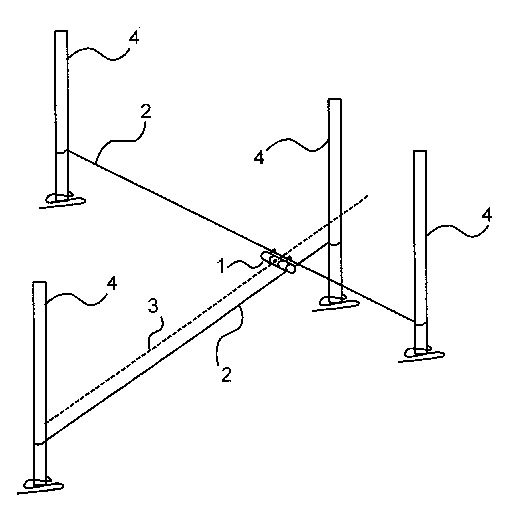
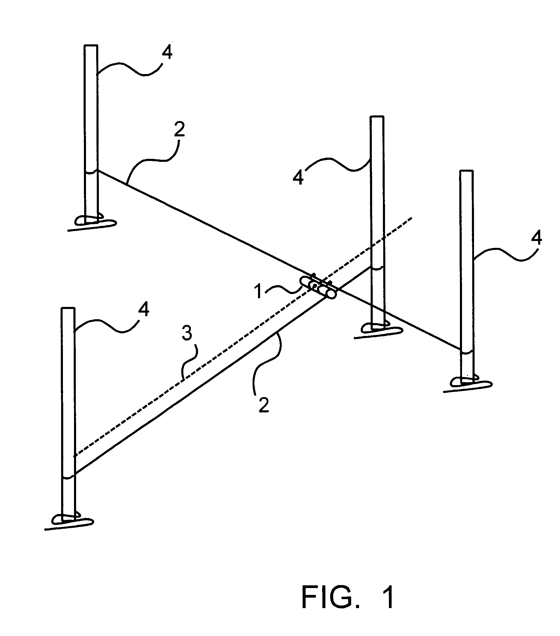
[0036]FIG. 1 shows a laser device 1 according to at least one embodiment of the present invention on a string or wire 2 tied between two stakes or posts 4 to define a corner. The laser device 1 is hung from the string 2 and projects a laser beam 3 out two sides to define a line substantially perpendicular to the string 2. Two additional stakes 4 are placed in the ground in the path of the laser beam 3. An additional string 2 is then tied between the two additional stakes 4, and thus a 90 degree angle is defined by the two strings 2. The intersection of the two strings 2 defines a corner for a square or rectangular building foundation. The process can be repeated for each of the other three corners.

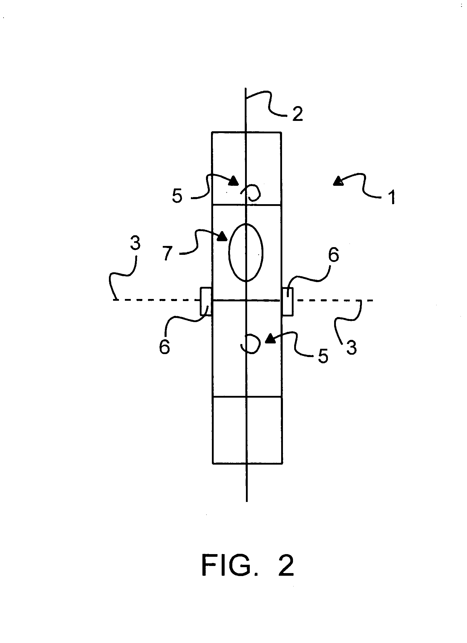
[0037]FIG. 2 shows a top close-up view of the laser device 1 shown in FIG. 1. The laser device 1 is hung from the string 2 by ho...


PUM


Abstract

An arrangement comprising a laser projection device is used in determining the location of corners in constructing a foundation of a building or other structure. The arrangement is also used in positioning wooden beams perpendicular to one another in a floor frame or similar structure.

Description

[0001]U.S. Patent Application to be filed under 35 U.S.C. §111 claiming priority from U.S. Provisional Patent Application No. 60 / 480,624, filed Jun. 23, 2003.BACKGROUND OF THE INVENTION[0002]1. Field of the Invention[0003]The present invention relates to an arrangement for use in determining the location of corners in constructing a foundation of a building or other structure. The present invention further relates to an arrangement for use in positioning wooden beams for a floor frame or similar structure.[0004]2. Background Information[0005]In construction, it is well known that establishing a secure and well designed foundation is essential in constructing buildings, homes, and other large structures. Poorly designed foundations often create difficulty in construction and lessen the stability of the structure. It is very important to lay a foundation in the ground that corresponds as exactly as possible to the shape and dimensions of the structure to be built. Since most buildings...

Claims


Application Information

Patent Timeline
Patent Type & Authority Patents(United States)
IPC IPC(8): G01C15/02G01C15/00
CPCG01C15/004Y10S33/21
Inventor ARMSTRONG, TIMOTHY D.HATHAWAY, GLENN T.
Owner ARMSTRONG TIMOTHY D
Why Eureka
Try Eureka