Mono control lift and tilt mechanism for horizontal blinds

a technology which is applied in the field of mono-controlled lifting and tilting mechanism for horizontal window blinds, can solve the problems of limiting the application of the device, difficult structure manufacturing, and large number of prior art mono-controlled lifting and tilting mechanism problems, and achieve the effect of reducing frictional hold

Inactive Publication Date: 2006-11-21
ROLLERASE INC
View PDF41 Cites 44 Cited by
  • Summary
  • Abstract
  • Description
  • Claims
  • Application Information

AI Technical Summary

Benefits of technology

[0009]A still further objective is to provide such a device that is economical and simple to manufacture.
[0012]The apparatus also preferably includes a means for tilting the slats that works in conjunction with part of the rotation of the cord-gathering shaft. A tilting drum fixed to a ladder cord raises and lowers alternate sides of the ladder cord when a drum key on the tilting drum is forced to move by the rotation of a torsion spring frictionally wrapped on an axle portion of the cord-gathering shaft. The drum key is positioned between the moving ends of a torsion spring. The axle rests in a support with a brace to prevent longitudinal movement of the axle portion but permit rotation. A means for limiting the rotation of the torsion spring on the support limits the arc of the tilt of the slats by reducing the frictional hold of the torsion spring on the axle.

Problems solved by technology

There are a limited number of prior art mono-controlled lifting and tilting mechanisms.
However, the complex structure of the tilter, which itself provides the varying frictional force on the shaft as a function of the weight of the slats of the blind, limits the application of the device.
The structure is difficult to manufacture and may not be appropriate for heavier blinds because the weight makes tilting more difficult.
Moreover, when winding the lifting cord, unnecessary transverse movement in addition to rotation is utilized to manage the coils of the lifting cord.
However, the system does not provide a workable solution for managing a lifting cord.
Moreover, tape lift systems are not practical for lifting some blinds such as large wood blinds.
Inner holes in the wood have inherently very sharp edges that cause cutting of the tape and will lead to lift failure.
However, tilting horizontal slats with a V-groove device was never a preferred way of achieving a tilt.
The positioning of the slats cannot be accurately controlled.
Sometimes, especially on lightweight blinds, the device is not reliable because almost the entire weight of the blind in being supported by the lift cord.
This leaves the ladder cord with out much tension in the V-groove and can lead to tilt failure.

Method used


Image

  • Mono control lift and tilt mechanism for horizontal blinds
  • Mono control lift and tilt mechanism for horizontal blinds
  • Mono control lift and tilt mechanism for horizontal blinds

Examples


Embodiment Construction

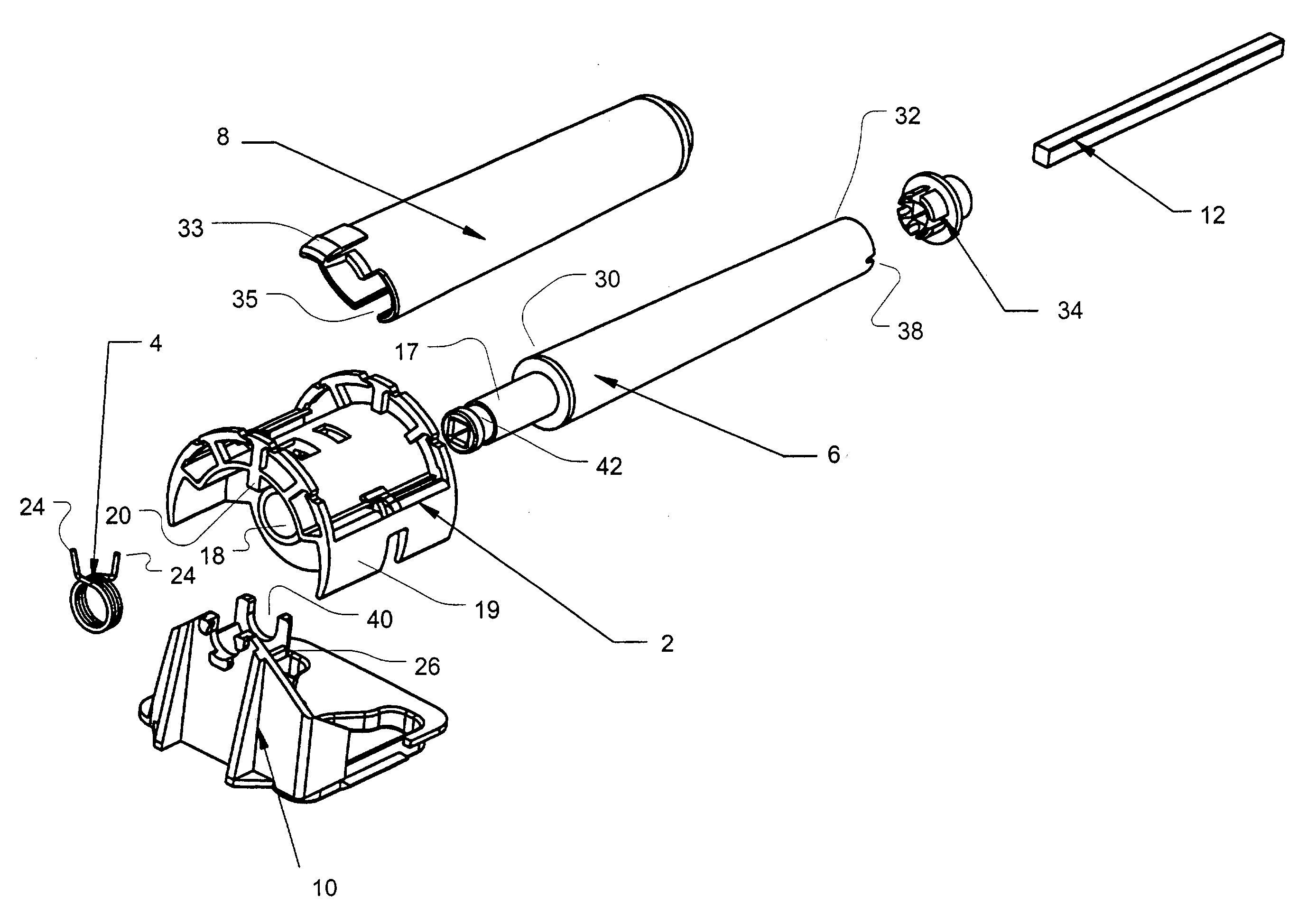
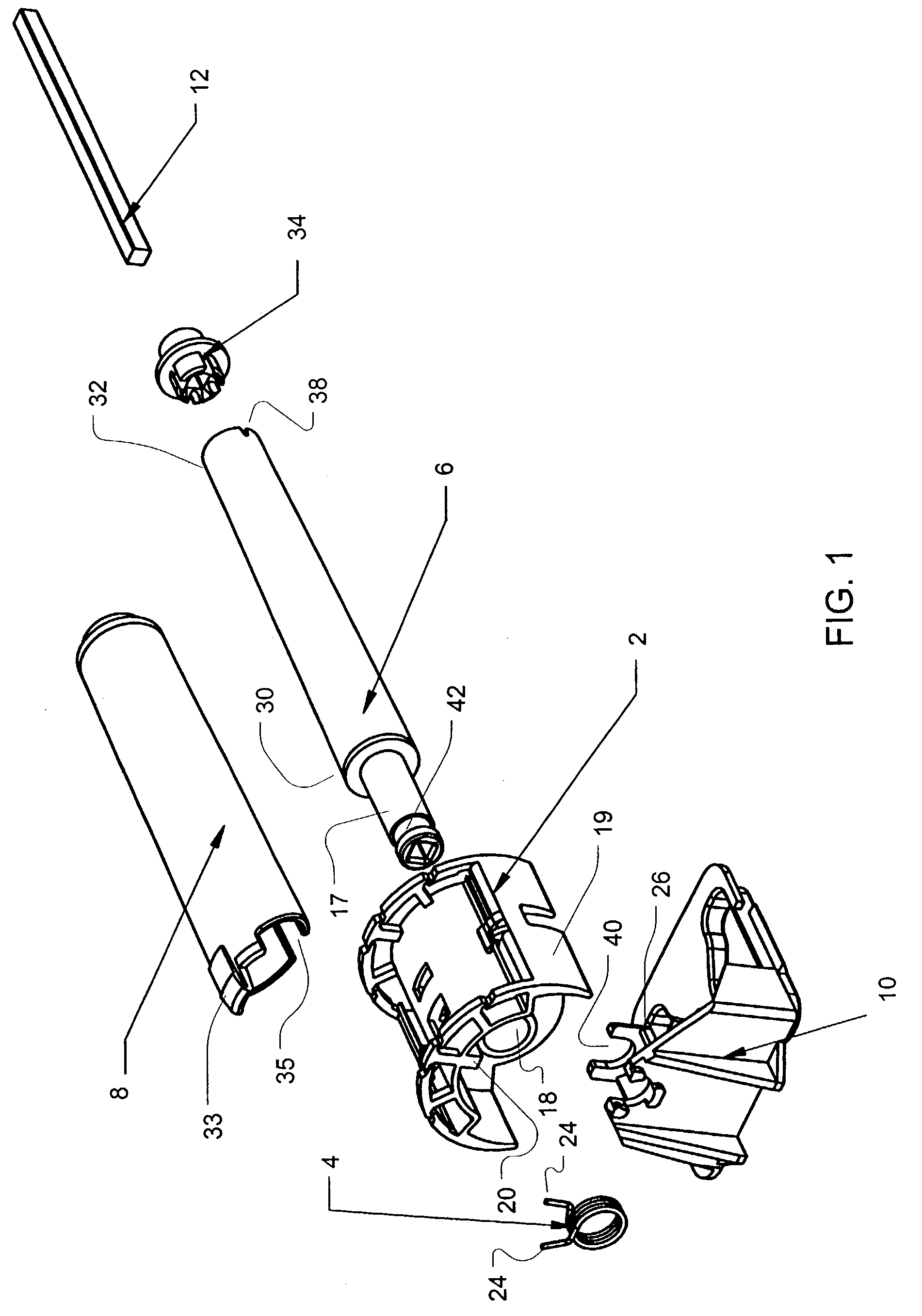
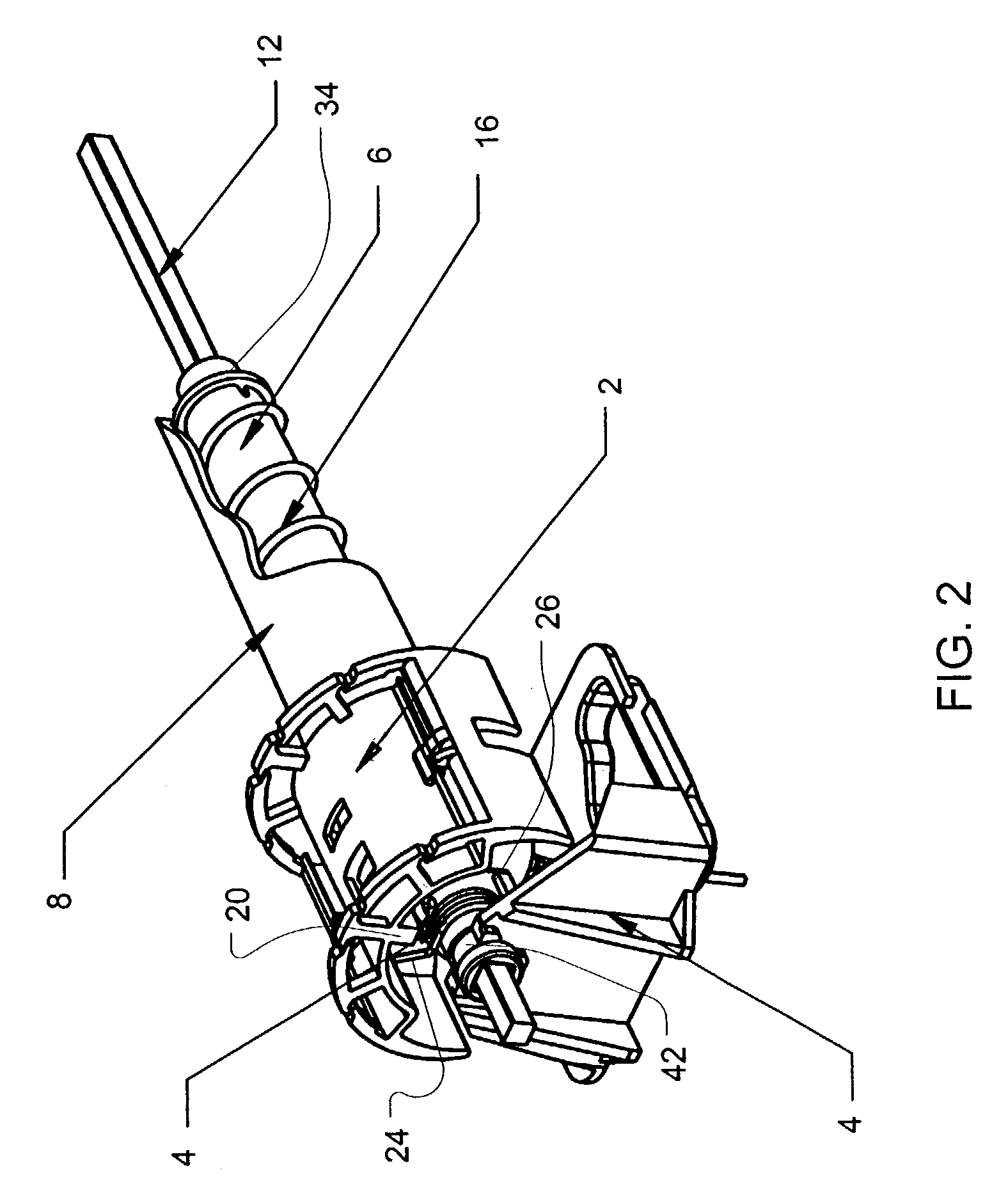
[0026]As illustrated in FIGS. 1–4, the invention includes a horizontal blind control that includes a tilting drum 2, torsion spring 4, cord-gathering shaft 6, cord cover 8 and support cradle 10. The components may be installed in a headrail H of a blind B. When combined with a turning shaft 12, a clutch 13 to rotate the shaft, a ladder cord 14 or ladder tape, a lifting cord 16, the components perform the dual functions of lifting the slats S of the blind B and / or tilting the slats S of the blind B to provide the desired level of shading or obstruction of light through a window on which the blind is installed. The preferred embodiment of each of the structures of the above components and a description of their operation are each addressed in turn.

[0027]The tilting drum 2 as the name implies is a component involved in achieving the function of tilting the slats S. The tilting drum 2 is configured to rest within the support cradle 10 when combined with the cord-gathering shaft 6 such t...


PUM


Abstract

The invention includes apparatus for controlling the lift and tilt of a horizontal window blind. A tilting drum, conic cord-gathering shaft, torsion spring and support cradle may be combined to provide lift and tilt adjustment with a single rotational control. An angular surface near one end of the cord-gathering shaft deflects winding coils of a lifting cord down the length of the cone. The torsion spring and spring stops in the device allow tilt adjustment to take place in conjunction with the rotation of the cord-gathering shaft. The preferred embodiment includes a cord cover to guide the coils as the diameter of the cord-gathering shaft decreases.

Description

[0001]This application claims the priority date of U.S. provisional patent application Ser. No. 60 / 367,308 filed on Mar. 25, 2002.FIELD OF THE INVENTION[0002]The invention relates to the field of window blinds. More specifically, the invention is a mechanism for a horizontal window blind for controlling the lift of the blind slats as well as the tilt of the blind slats.BACKGROUND OF THE INVENTION[0003]In the construction of horizontal blinds, particularly in wood blinds, two kinds of controls are desired. The blind should have a control to lift the slats of the blind. In addition, the blind should permit control over the tilt of the slats. Traditionally, two separate operating mechanisms were used to provide the desired control. One device would exclusively control the lifting of the blind while another independent device would control the tilt position of the slats. A single mechanism controlling both functions is preferred.[0004]There are a limited number of prior art mono-control...

Claims


Application Information

Patent Timeline
Patent Type & Authority Patents(United States)
IPC IPC(8): E06B9/30E06B9/303E06B9/308
CPCE06B9/303E06B9/308E06B2009/3225
Inventor FRACZEK, RICHARD
Owner ROLLERASE INC
Why Eureka
Try Eureka