Firefighting equipment

a firefighting equipment and mobile technology, applied in watering devices, horticulture, agriculture, etc., can solve the problems of inability to effectively fight difficulty in tackling fires in tall buildings, and sometimes impossible, so as to achieve the effect of preventing fires and reducing the risk of fires

Inactive Publication Date: 2006-11-21
MOSES LINNIE L
View PDF12 Cites 21 Cited by
  • Summary
  • Abstract
  • Description
  • Claims
  • Application Information

AI Technical Summary

Benefits of technology

[0009]In another embodiment of the invention, the fire truck is an articulated vehicle with a pusher blade attached to its front end. The blade and articulated vehicle construction allows it to be an effective “off road” vehicle capable of moving obstacles out of the way of the fire truck and enabling the truck to traverse terrain conventional fire trucks are unable to traverse to better enable the truck to reach previously inaccessible areas to fight a fire.

Problems solved by technology

Fighting fires in tall buildings is extremely difficult.
Depending on the location of the fire (i.e., on a streetside of the building where the fire is accessible, or away from a streetside where it is not), positioning fire fighting equipment close enough to the location of the fire so to be effective in fighting it can be very difficult, and sometimes impossible.
If the fire is located away from the opening into which water is directed, the water may not reach the fire and will no therefore be very effective in putting out the fire.
Overcoming these obstacles has heretofore been difficult to do, if at all, unless firefighters can reach the floor and breach the walls and partitions with pickaxes, spiked poles, or other equipment.
Besides these problems, another difficulty is that fire trucks, especially those used in metropolitan areas, are currently not designed for off-road use.
That is, they generally must remain on a street and cannot readily be driven close to a building which is setback from the street any appreciable distance and erected on a hill, for example.
Accordingly where the building is not adjacent a street, or there is an elevation change between street level and the building, it becomes significantly more difficult to fight a fire in the building.

Method used


Image

  • Firefighting equipment
  • Firefighting equipment
  • Firefighting equipment

Examples


Embodiment Construction

[0016]The following detailed description illustrates the invention by way of example and not by way of limitation. This description will clearly enable one skilled in the art to make and use the invention, and describes several embodiments, adaptations, variations, alternatives and uses of the invention, including what I presently believe is the best mode of carrying out the invention. As various changes could be made in the above constructions without departing from the scope of the invention, it is intended that all matter contained in the above description or shown in the accompanying drawings shall be interpreted as illustrative and not in a limiting sense.

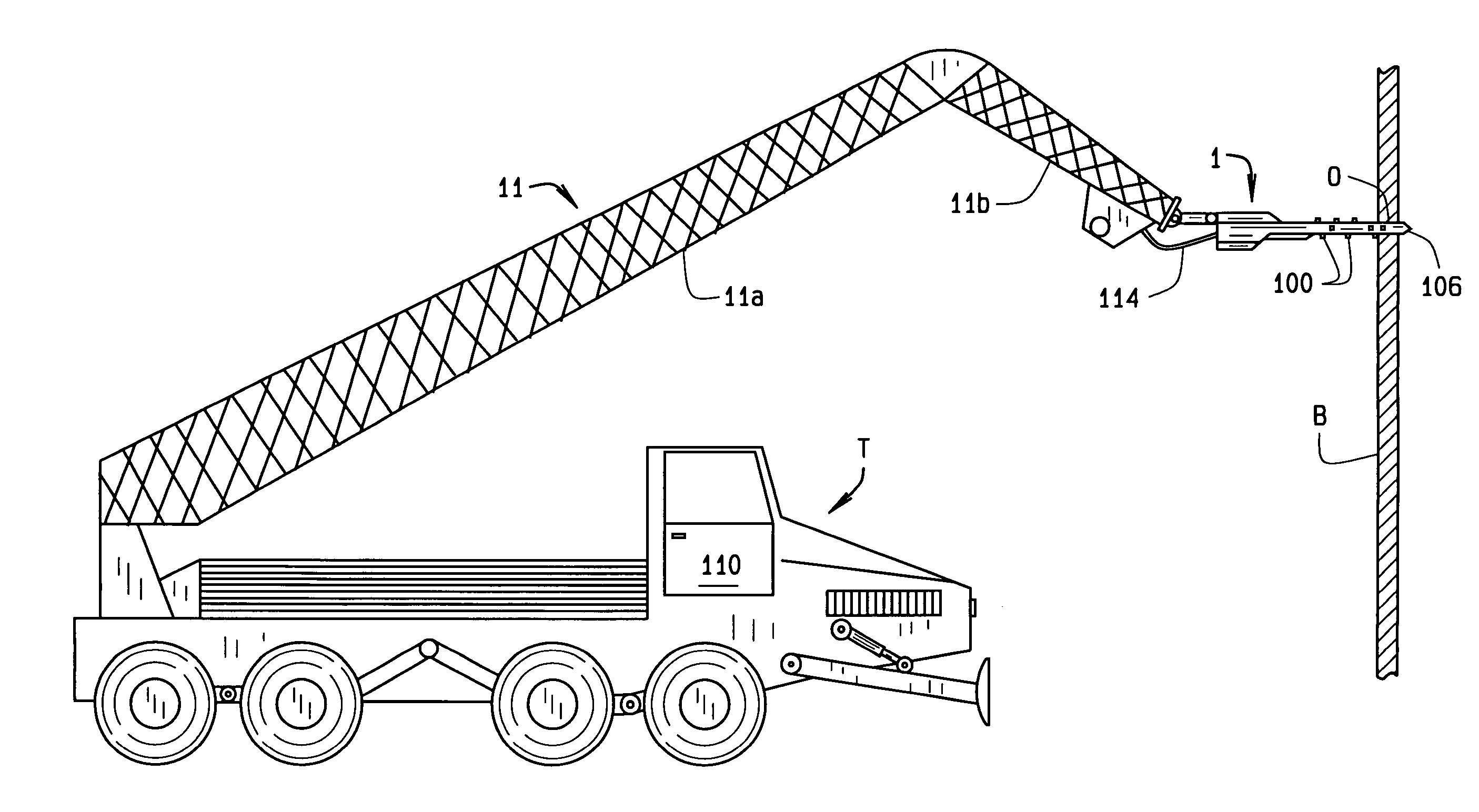
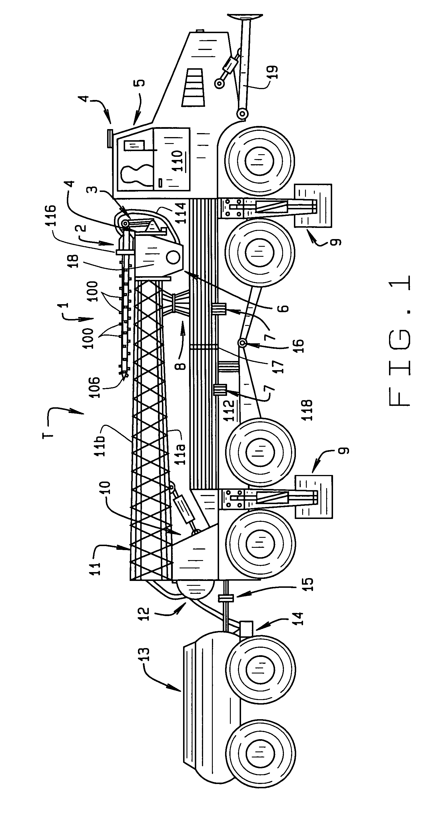
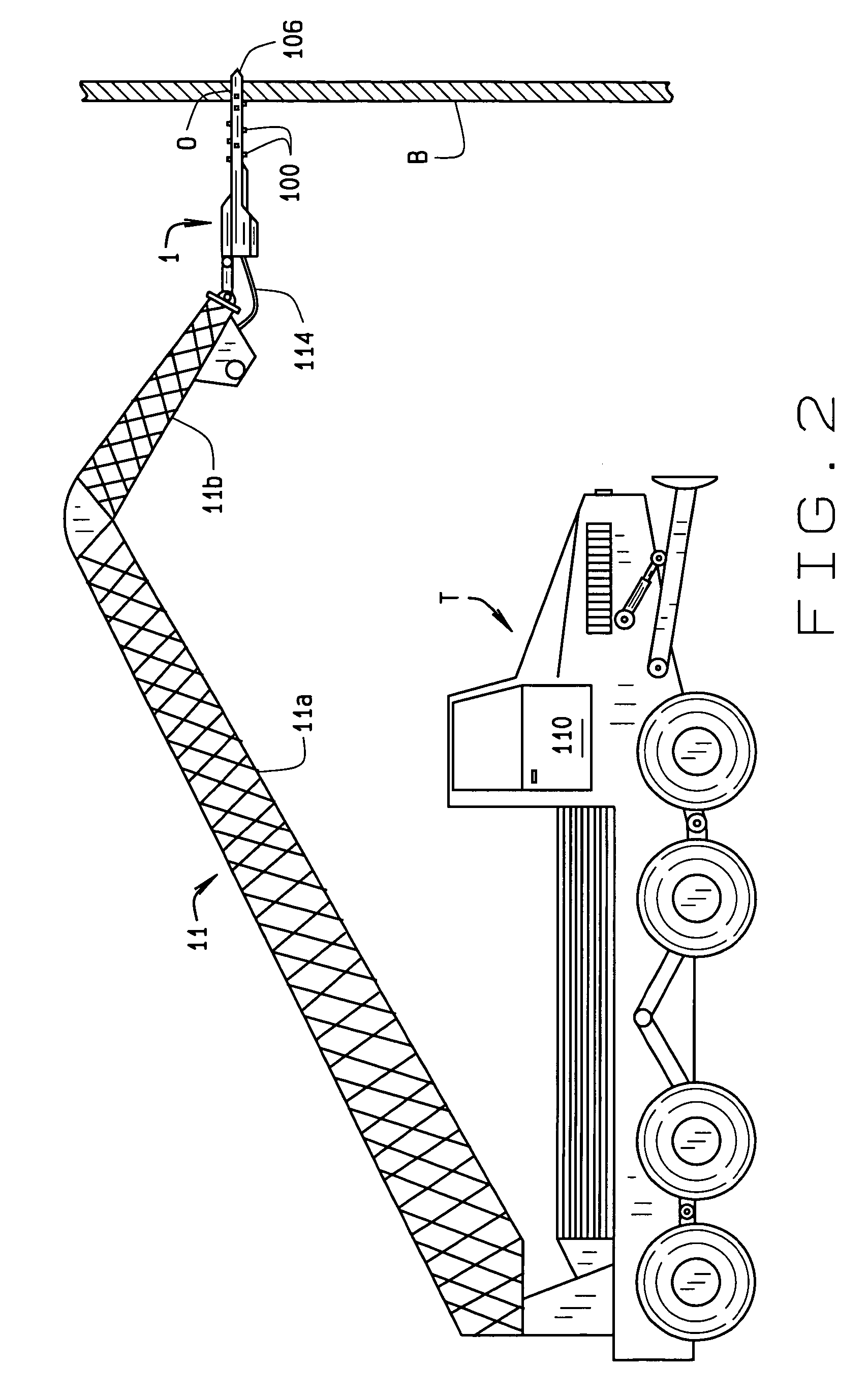
[0017]Referring to the drawings, an articulated fire truck T of the present invention includes a three-in-one remote control nozzle assembly indicated generally 1. The nozzle assembly provides a hammer drill with a side cutting capability combined with a high-pressure water gun. When extended against the side of a building B, ...


PUM


Abstract

An articulated fire truck (T) has an extendible and retractable boom (11) mounted on the truck and extendible to a height above the ground where a fire is burning within a building (B). A drill assembly (1) is affixed to the end of the boom for drilling through a sidewall of the building into the building's interior. The drill assembly is maneuverable to drill straight through the sidewall as well as up and down and sideways so to provide an opening into the interior of the building sufficiently large that a nozzle attached to the drill assembly can readily spray water or a fire retardant material into the interior to extinguish the fire. The drill assembly has drill bits (100) located completely about the circumference of the drill assembly to facilitate up-and-down and side-to-side cutting to more quickly penetrate into the building's interior.

Description

CROSS REFERENCE TO RELATED APPLICATIONS[0001]This application is based upon Provisional Patent Application 60 / 551,707 filed Mar. 10, 2004.STATEMENT REGARDING FEDERALLY SPONSORED RESEARCH OR DEVELOPMENT[0002]Not applicableBACKGROUND OF THE INVENTION[0003]This invention relates to mobile firefighting equipment such as a fire truck equipped to fight fires in tall buildings; and more particularly, to a retrofitted or original equipment (OE) fire truck employing the equipment to breach walls on both the outside or the inside of a building. When the walls are breached, water or a fire retardant gas or foam is sprayed through in-line and / or peripheral nozzles onto a fire to extinguish it.[0004]Fighting fires in tall buildings is extremely difficult. Depending on the location of the fire (i.e., on a streetside of the building where the fire is accessible, or away from a streetside where it is not), positioning fire fighting equipment close enough to the location of the fire so to be effecti...

Claims


Application Information

Patent Timeline
Patent Type & Authority Patents(United States)
IPC IPC(8): A62C31/22A62C27/00
CPCA62C27/00A62C31/22
Inventor MOSES, LINNIE L.
Owner MOSES LINNIE L
Why Eureka
Try Eureka