Apparatus And Method For Microresistivity Imaging In Nonconductive Drilling Fluid

a technology of resistivity imaging and drilling fluid, which is applied in the field of resistivity logging measurements, can solve the problems of increasing the impedance of the conductor

Active Publication Date: 2013-09-12
SCHLUMBERGER TECH CORP
View PDF22 Cites 12 Cited by
  • Summary
  • Abstract
  • Description
  • Claims
  • Application Information

AI Technical Summary

Benefits of technology

[0009]Exemplary embodiments of the present invention may advantageously provide several technical advantages. For example, logging tools in accordance with the present invention may be advantageously enable microresistivity measurements of a subterranean formation in the presence of nonconductive drilling fluid. Moreover, as compared to a conventional four-electrode sensor, embodiments of the present invention generally form a considerably smaller current loop such that the self inductance affect of the current loop on the microresistivity measurement tends to be significantly reduced. Embodiments of the invention also tend to be advantageously less sensitive to censor standoff than conventional four-electrode sensors. A further advantage of the present invention over conventional four-electrode sensors is that the transmitting and receiving conductors are not in direct contact with drilling fluids, thus avoiding electrochemical effects that can take place at the exposed surface of the conductor. These effects are known to typically increase the impedance of the conductor. As a result of the foregoing advantages, microresistivity measurements made with sensors in accordance with the present invention therefore tend to have increased sensitivity to the true formation resistivity.
[0010]In one aspect the present invention includes a downhole microresistivity logging tool. The tool includes a transmitter coil and a receiver coil deployed on a logging tool body. The transmitter coil includes an electrical conductor wound about a magnetically permeable core. The electrical conductor is connected to a high frequency alternating current generator deployed in the tool body. The receiver coil also includes an electrical conductor wound about a magnetically permeable core, the electrical conductor being connected to a high frequency alternating voltage sensor deployed in the tool body. Each of the transmitter and receiver coils defines a coil axis that is substantially perpendicular to the longitudinal axis of the tool body.
[0011]In yet another aspect, the present invention includes a microresistivity logging while drilling tool. The logging while drilling tool includes a microresistivity logging sensor deployed on a logging while drilling tool body. The microresistivity sensor includes a transmitter coil and a receiver coil, each of which defines a coil axis that is substantially perpendicular to the longitudinal axis of the tool body. The transmitter coil includes an electrical conductor wound about a magnetically permeable core, the electrical conductor being connected to a high frequency alternating current generator deployed in the tool body. The receiver coil includes an electrical conductor wound about a magnetically permeable core, the electrical conductor being connected to a high frequency alternating voltage sensor deployed in the tool body.
[0012]The foregoing has outlined rather broadly the features and technical advantages of the present invention in order that the

Problems solved by technology

These effects are known to typically increase the impedance of the conductor.

Method used


Image

  • Apparatus And Method For Microresistivity Imaging In Nonconductive Drilling Fluid
  • Apparatus And Method For Microresistivity Imaging In Nonconductive Drilling Fluid
  • Apparatus And Method For Microresistivity Imaging In Nonconductive Drilling Fluid

Examples


Embodiment Construction

[0021]Referring now to FIG. 1 through 7, exemplary embodiments of the present invention are depicted. With respect to FIG. 1 through 7, it will be understood that features or aspects of the embodiments illustrated may be shown from various views. Where such features or aspects are common to particular views, they are labeled using the same reference numeral. Thus, a feature or aspect labeled with a particular reference numeral on one view in FIG. 1 through 7 may be described herein with respect to that reference numeral shown on other views.

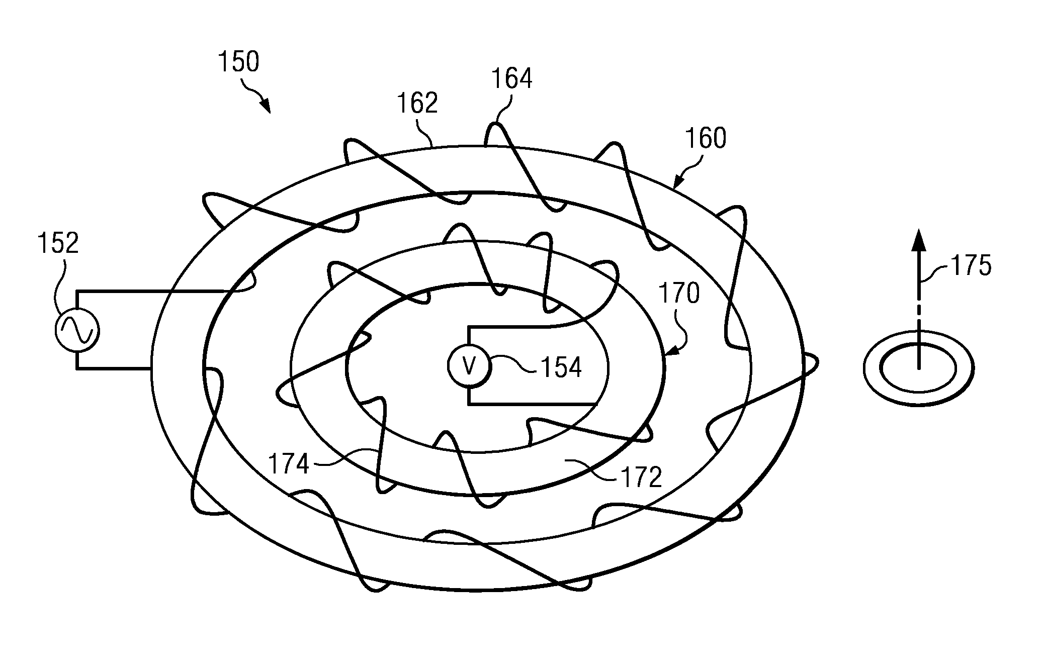
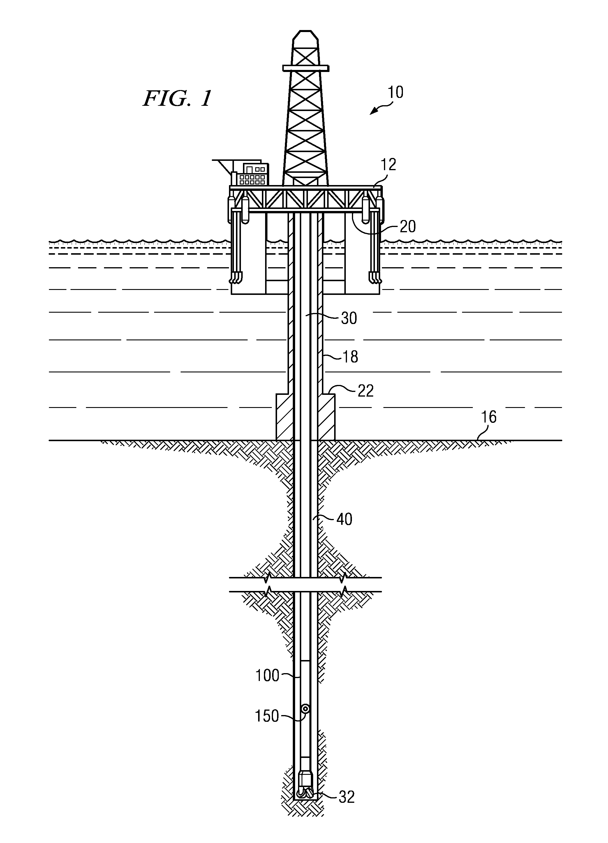
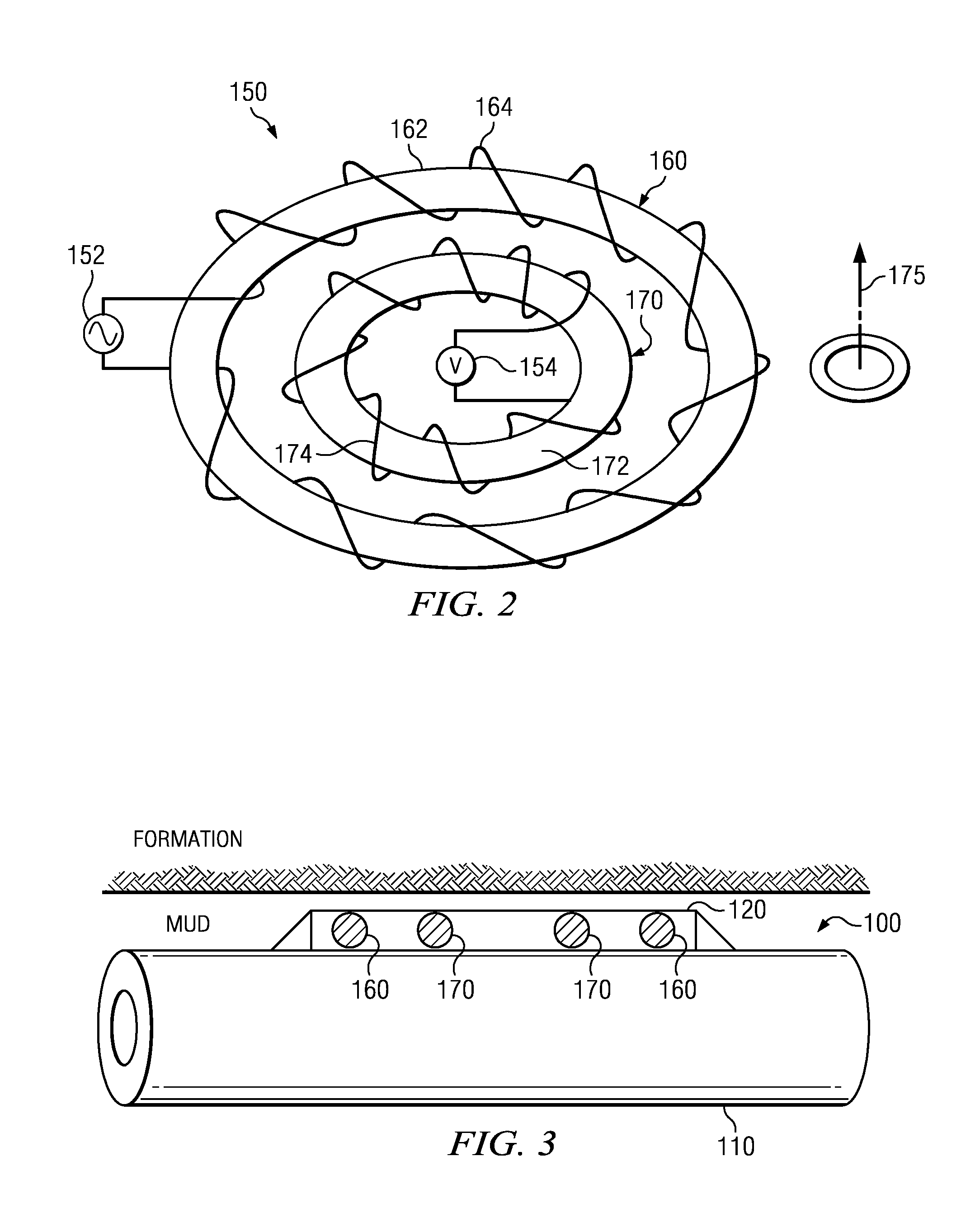
[0022]FIG. 1 depicts one exemplary embodiment of a microresistivity logging while drilling tool 100 in use in an offshore oil or gas drilling assembly, generally denoted 10. In FIG. 1, a semisubmersible drilling platform 12 is positioned over an oil or gas formation (not shown) disposed below the sea floor 16. A subsea conduit 18 extends from deck 20 of platform 12 to a wellhead installation 22. The platform may include a derrick and a hoisting a...


PUM


Abstract

A microresistivity logging tool includes a transmitter coil and at least one receiver coil deployed on a tool body. The transmitter coil and receiver coil define axes that are preferably substantially perpendicular to the tool axis.

Description

RELATED APPLICATIONS[0001]This application claims the benefit of: U.S. Provisional Application Ser. No. 61 / 377,162 filed Aug. 26, 2010 and entitled Apparatus and Method for Micro resistivity Imaging in Non-Conducting Mud.FIELD OF THE INVENTION[0002]The present invention relates generally to microresistivity logging measurements. More particularly, embodiments of the invention relate to a logging while drilling tool suitable for making microresistivity measurements non-conductive drilling fluids.BACKGROUND OF THE INVENTION[0003]The use of electrical measurements in prior art downhole applications, such as logging while drilling (LWD) and wireline logging applications, is well known. Such techniques may be utilized, for example, to determine a subterranean formation resistivity, which, along with formation porosity measurements, may be used to indicate the presence of hydrocarbons in the formation. It is known in the art that porous formations having a high electrical resistivity ofte...

Claims


Application Information

Patent Timeline
Patent Type & Authority Applications(United States)
IPC IPC(8): G01V3/10
CPCG01V3/10G01V3/28
Inventor WANG, TSILI
Owner SCHLUMBERGER TECH CORP
Why Eureka
Try Eureka