Crawler device

Inactive Publication Date: 2006-11-21
CHARLES STARK DRAPER LABORATORY
View PDF12 Cites 46 Cited by
  • Summary
  • Abstract
  • Description
  • Claims
  • Application Information

AI Technical Summary

Benefits of technology

[0007]In one preferred embodiment, each segment of the crawler device has two drive wheels disposed on the two opposite sides of the segment. In another preferred embodiment, each segment of the crawler device has two sets of drive wheels disposed at two opposite sides of the segment, each set having t

Problems solved by technology

Tracked tank design has been successfully used for travel over relatively smooth terrain, but it fails to traverse extremely rugged terrain or relatively large obstacles, for example, as might be encountered in the rub

Method used


Image

  • Crawler device
  • Crawler device
  • Crawler device

Examples


Embodiment Construction

[0033]For the purposes of promoting an understanding of the present invention, reference will now be made to the embodiments illustrated in the drawings and specific language will be used to describe the same.

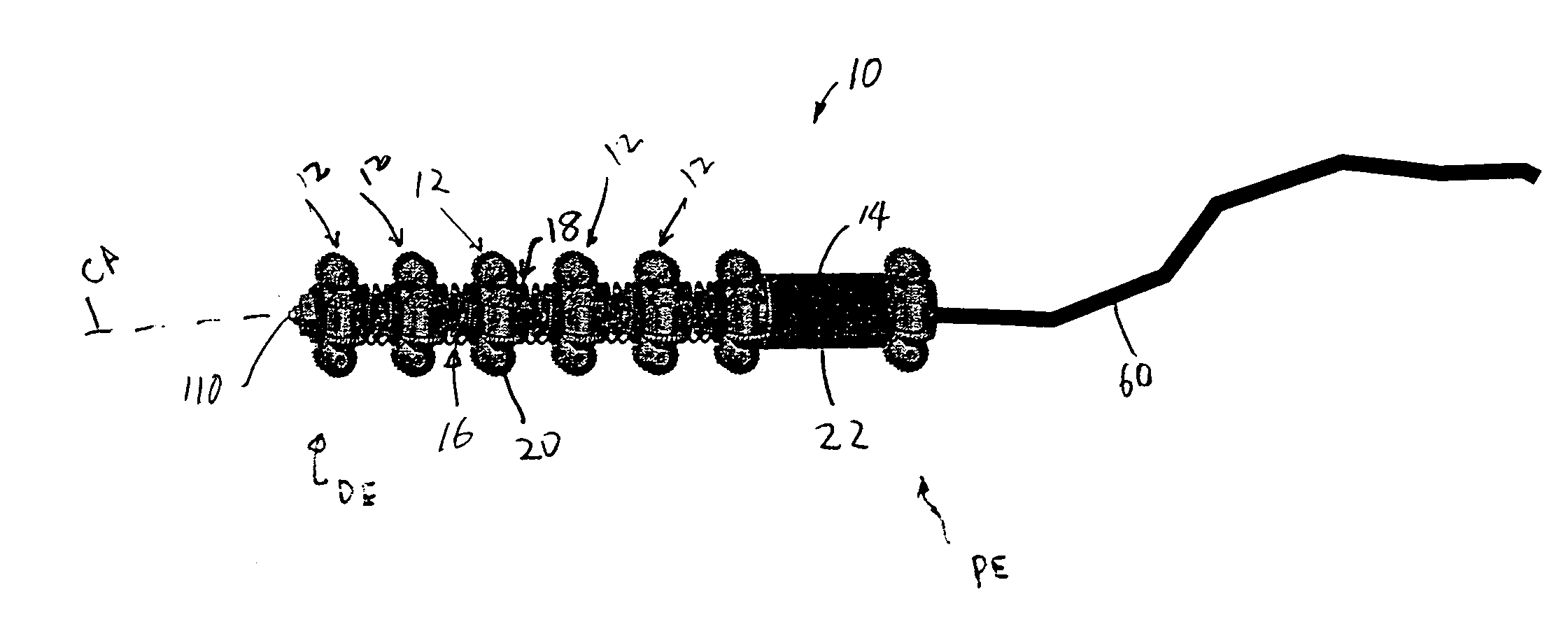
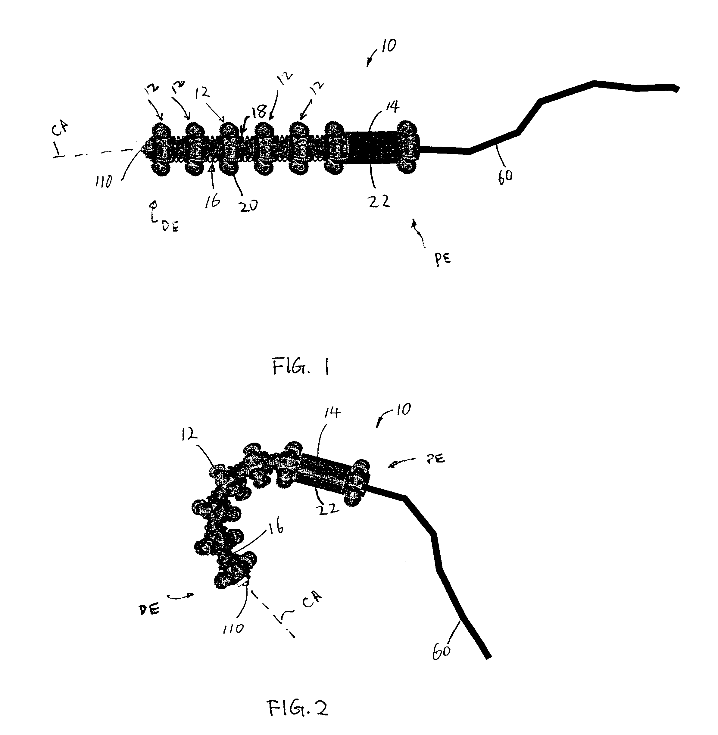
[0034]FIG. 1 illustrates a preferred embodiment of a crawler device 10 in accordance with the present invention. As shown in FIG. 1, the crawler device 10 includes a plurality of repeating segments 12 and a motor 14 disposed over one common drive shaft 16, which extends along a curvilinear central axis CA (which is illustrated as straight in FIG. 1 and curved in FIG. 2). Each segment 12 has its own wheel assembly 18 which includes a plurality of drive wheels 20. The motor 14 is disposed within a drive unit (housing) 22, which is positioned near or at a proximal end of the drive shaft 16.

[0035]The crawler device 10 extends along axis CA between a proximal end PE and a distal end DE. The repeating segments 12 of the crawler device 10 are preferably joined pairwise by articulated ...


PUM


Abstract

A crawler device for traversing in a confined environment, searching victims or inspecting defections, comprises an elongated flexible drive shaft extending along a central axis between a proximal end and a distal end, a motor operatively connected to the drive shaft for turning the drive shaft, and a plurality of segments disposed over the drive shaft. Any two adjacent segments are joined by an articulate joint. Each segment has a wheel assembly including drive wheels. At least two segments further include a gear assembly operatively connecting the wheel assembly to the drive shaft. Turning the drive shaft provides distributed traction force to the drive wheels of the at least two segments, and thereby drives the crawler device.

Description

CROSS-REFERENCE TO RELATED APPLICATION[0001]This application claims the benefit of priority from U.S. Provisional Application Ser. No. 60 / 415,347, filed Oct. 2, 2002.FIELD OF THE INVENTION[0002]The invention generally relates to a crawler device, more specifically, to a wheeled crawler device for traversing in confined circumstances.BACKGROUND OF THE INVENTION[0003]Crawler devices have been used for carrying camera devices, microphones, nutrients, and medications to confined space, or hazardous space, such as conduits, pipes, rubble of collapsed structures (buildings, highways, etc.). In the prior art, an elongated, articulated so called “micro-tank” has been used to inspect pipes and search for victims in earthquake rubble. The micro-tank incorporates a single unit or a plurality of repeating units connected by joints. Each unit has its own drive motor which drives oval tracks through a gear mechanism. The unit may be powered by batteries carried on the unit and controlled remotely...

Claims


Application Information

Patent Timeline
IPC IPC(8): B62D61/10
CPCB62D57/00B62D61/10B62D63/02
Inventor KERREBROCK, PETER A.ANDERSON, JAMIE M.MCFARLAND, JR., WILLIAM W.OGRODNIK, THOMAS G.
Owner CHARLES STARK DRAPER LABORATORY
Why Eureka
Try Eureka