Segmented monitor

a monitor and segment technology, applied in the field of segmented monitors, can solve the problems of limiting their usefulness, high friction to overcome, unstable position, etc., and achieve the effect of minimizing rotational torque on the connection

Active Publication Date: 2006-11-21
TASK FORCE TIPS
View PDF18 Cites 39 Cited by
  • Summary
  • Abstract
  • Description
  • Claims
  • Application Information

AI Technical Summary

Benefits of technology

[0021]It is a further object of this invention to provide a segmented monitor with a controlling mechanism that is substantially free from restraining forces resulting from internal pressure or nozzle reaction.
[0022]It is another object of this invention to provide a compact monitor with minimum turbulence and friction losses to produce a discharge stream which reaches a greater distance.
[0024]These and other objects are accomplished by a firefighting monitor for redirecting a flow of fluid from a pressurized fluid source through a conduit, the conduit comprising four consecutive segments rotatably connected in series wherein an axis of rotation is provided at each connection between the four segments. The conduit comprises a first segment connected to the fluid source followed in series by a second segment connected to an outlet of the first segment, a third segment connected to an outlet of the second segment and a fourth segment connected to an outlet of the third segment forming consecutively at each connection a first axis of rotation, a second axis of rotation and a third axis of rotation respectively; the monitor includes a redirection of an azimuth angle of the conduit by an azimuth rotation between the first segment and the second segment on the first axis of rotation, and the monitor further includes a redirection of an elevation angle of the conduit by a first rotation between the second segment and the third segment on the second axis of rotation in a first direction and by a second rotation between the third segment and the fourth segment on the third axis of rotation in an opposite direction to the first direction. The fourth segment comprises a discharge end having a discharge centerline which intersects with a centerline of the second axis of rotation and a centerline of the third axis of rotation, thereby minimizing rotational torque on the connection between the second segment and the third segment and the rotational torque on the connection between the third segment and the fourth segment.
[0025]The redirection of an elevation angle of the monitor includes a synchronization of the first rotation between the second segment and the third segment and the second rotation between the third segment and the fourth segment in counter rotating directions to obtain approximately planar motion of the discharge centerline during the elevation angle redirection. The fourth segment comprises a discharge end having a discharge centerline that is approximately co-planer with the first axis of rotation thereby minimizing rotational torque on the connection between the first segment and the second segment. The monitor comprises an angle of approximately 68 degrees between the first axis of rotation and the second axis of rotation, an angle of approximately 34 degrees between the second axis of rotation and the third axis of rotation, and an angle of approximately 34 degrees between the third axis of rotation and the discharge centerline. The monitor comprises an angle between the second axis of rotation and the third axis of rotation and a substantially equal angle between the third axis of rotation and the discharge centerline. The second segment comprises a predetermined curvature adjacent to an outlet end, the third segment comprises a predetermined curvature between an inlet end and the outlet end, and the fourth segment comprises a first curvature extending from an inlet end and a second curvature extending to an outlet end of the fourth segment. The fourth segment comprises the first curvature and the second curvature to minimize rotational torque on the connection between the first segment and the second segment. The predetermined curvature of the second segment comprises approximately 68 degrees, the predetermined curvature of the third segment comprises approximately 34 degrees, and the first curvature of the fourth segment comprises approximately 73 degrees and the second curvature of the fourth curvature comprises approximately 39 degrees. At least one of the rotatable connections comprises a male / female ball race. The first segment is rotatably connected to the second segment by a first male / female ball race, the second segment is rotatably connected to the third segment by a second male / female ball race, and the third segment is rotatably connected to the fourth segment by a third male / female ball race. The second segment comprises an azimuth shaft assembly connected to a first turning device for adjusting the azimuth rotation, and the azimuth shaft assembly comprises a worm for engaging a worm wheel located on the circumference of the first segment. The synchronization comprises gears. The gears comprise bevel gears.

Problems solved by technology

Most ball-in-socket designs develop motion through a sliding motion between the ball and socket, thus tending to have high friction to overcome.
A single ball-in-socket is restricted to travels substantially less than 90 degrees from straight which limits their usefulness.
However, reaction forces on ball joints arranged in a series cause position to be unstable when the centerline of the nozzle reaction force does not pass through the centers of rotation.
However, the axle passing through the flowpath presents a disruption to the flow causing turbulence while the ball in socket arrangement is limited to relatively limited range of motion.
However, the ball joints would be difficult to move under pressure because of the sliding motion of the ball within their sockets.
In addition, the rotating joints would be difficult to move because of the eccentric loading of the nozzle reaction forces on the rotating joints.
In addition, flexible hoses are limited by compression set properties of the flexible hose material.
Adverse stresses exist within the hose for all positions other than neutral, which limits their degree of flexibility, and optimal storage position.
Because of their limitations, the use of the ball in socket devices and flexible hose mechanisms accounts for only a small percentage of the actual number of monitors commercially produced each year.
With such an ultra contorted flow path these bends produce severe turbulence which adversely effect friction loss, stream quality and range.
The flow path of this monitor comprises a plurality of turns which create undesirable turbulence and friction losses.

Method used


Image

  • Segmented monitor
  • Segmented monitor
  • Segmented monitor

Examples


Embodiment Construction

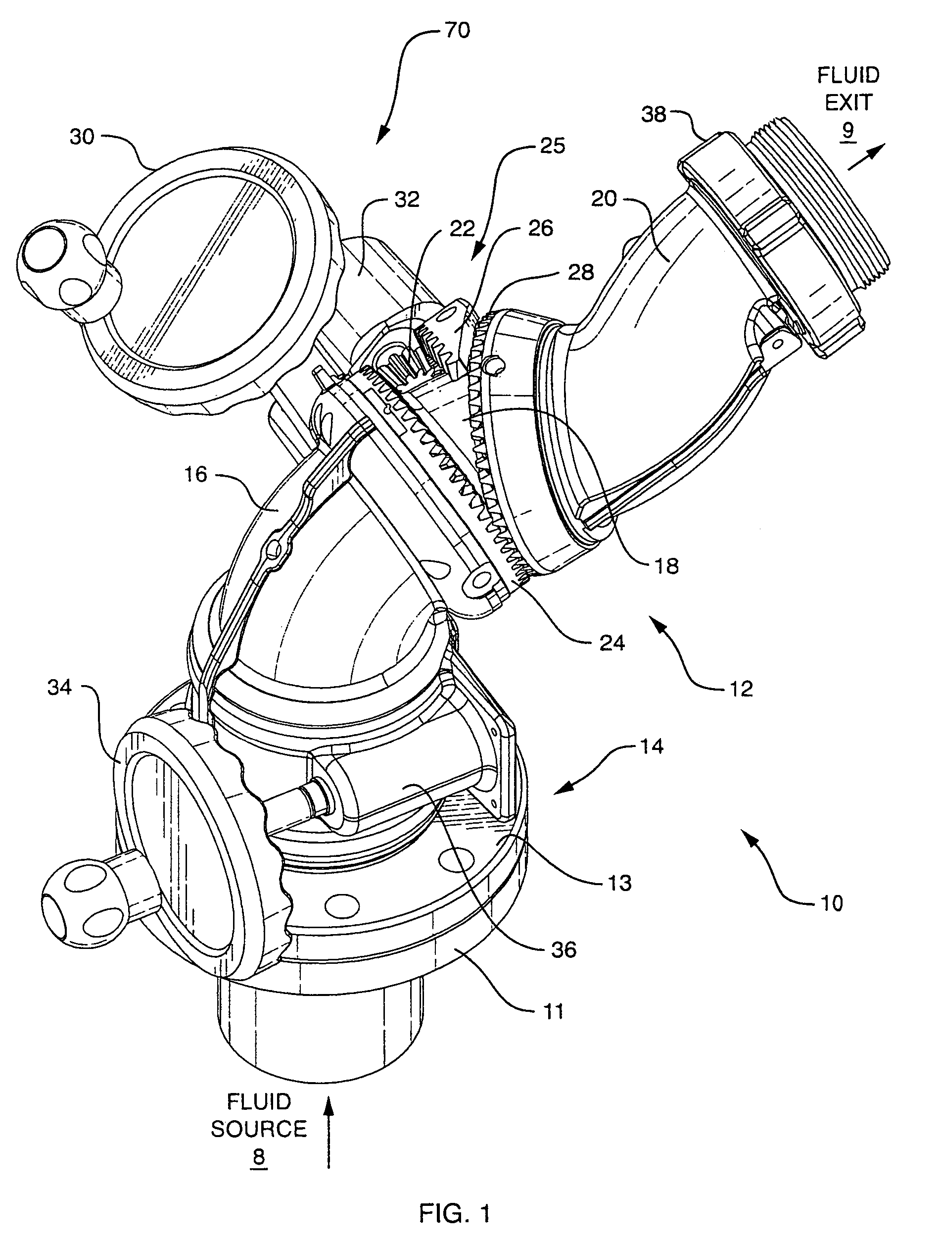
[0045]Referring to FIG. 1, a perspective view of a firefighting segmented monitor 10 is shown according to the invention. The segmented monitor 10 is a conduit used to position the trajectory of a pressurized fluid source 8 (usually water), received at an inlet end of a first segment or stationary segment 13, and the fluid is discharged at the fluid exit 9 and directed towards a target. The segmented monitor 10 in fire service is generally fitted with a nozzle in order to increase the velocity of the fluid and deliver a straight stream over considerable distance. The segmented monitor 10 is shown in the preferred embodiment as a nominal 4 inch size and rated for a maximum flow of 2000 gallons per minute. However, other sizes of the segmented monitor 10 may be implemented. With the centerline of the monitor's stationary segment 13 vertical (fluid flowing straight up), the range of discharge elevation of the segmented monitor 10 is from 46 degrees below horizontal to 90 degrees above ...


PUM


Abstract

A firefighting segmented monitor for redirecting a trajectory of a pressurized fluid discharge towards a target comprises a flowpath with minimum convolutions. The monitor flowpath comprises in series a stationary segment and three rotating segments including a lower segment, a middle segment and an upper segment connected in series each of which comprises a predetermined curvature. The lower segment swivels in one axis about the stationary segment. A nonorthogonal swivel is arranged on each end of the middle segment at the interfaces with the lower segment and the upper segment, and the swiveling of the middle and upper segments are synchronized with a single rotary input to produce an approximately planar elevational motion of the fluid discharge end of the monitor.

Description

BACKGROUND OF THE INVENTION[0001]1. Field of the Invention[0002]This invention relates generally to firefighting monitors and in particular to a compact segmented monitor having three nonorthogonal swivel joints, and minimal convolutions in the flowpath to reduce fluid pressure loss and to reduce overall turbulence of a discharge stream exiting from the segmented monitor.[0003]2. Description of Related Art[0004]A firefighting monitor is a conduit that is supplied with a pressurized fluid (usually water) at the inlet end and has a fire-fighting nozzle connected at the discharge end. The firefighting monitor's primary purpose is to allow the fluid exiting the nozzle to be redirected in both elevation and azimuth angles and then remain pointed at the desired target.[0005]Monitors may be installed in fixed locations, may be portable devices, or may be mounted on mobile equipment such as fire trucks, trailers, and the like. Monitors in the fire service are generally fitted with a nozzle ...

Claims


Application Information

Patent Timeline
Patent Type & Authority Patents(United States)
IPC IPC(8): B05B15/08A62C31/24B05B15/06B05B15/68
CPCA62C31/24B05B15/066Y10S285/912B05B15/652
Inventor STEINGASS, ROBERT W.KOLACZ, DAVID J.
Owner TASK FORCE TIPS
Why Eureka
Try Eureka