Differential device

a technology of differential devices and gears, applied in differential gearings, belts/chains/gearrings, differential gearings, etc., can solve the problems of little room for improvement, the drive force and stability of this kind of differential device, and the bevel gear drive structure is far from desirable, so as to increase the number of teeth and modulus of each train, increase the drive force and stability, and increase the size of gears

Inactive Publication Date: 2006-11-21
TAIWAN JET POWER INDAL
View PDF2 Cites 15 Cited by
  • Summary
  • Abstract
  • Description
  • Claims
  • Application Information

AI Technical Summary

Benefits of technology

[0007]The differential device revealed by this invention features an innovative design consisting of two trains of planet gears and central gears. They are geared with each other at several places and at average intervals. This can resolve the problems of traditional bevel gear differential devices and greatly enhance the drive force and stability. Meanwhile, increasing the size of gears can effectively increase the number of teeth and modulus of each train of gears. Accordingly, the driving friction can be easily controlled. The overall system is quite an improvement in terms of utilization and effectiveness.

Problems solved by technology

However, as the gearing drive between the bevel gear, the input shaft and two output shafts is single side direction, the drive force and its stability of this kind of bevel gear drive structure is far from desirable.
Furthermore, as far as a bevel gear is concerned, the augmentation of its size is less likely to bring about effective increases of such variables as modulus and number of teeth, which are critical for the increase of its friction.
Consequently, this kind of differential device has little room for any improvement.

Method used


Image

  • Differential device
  • Differential device
  • Differential device

Examples


Embodiment Construction

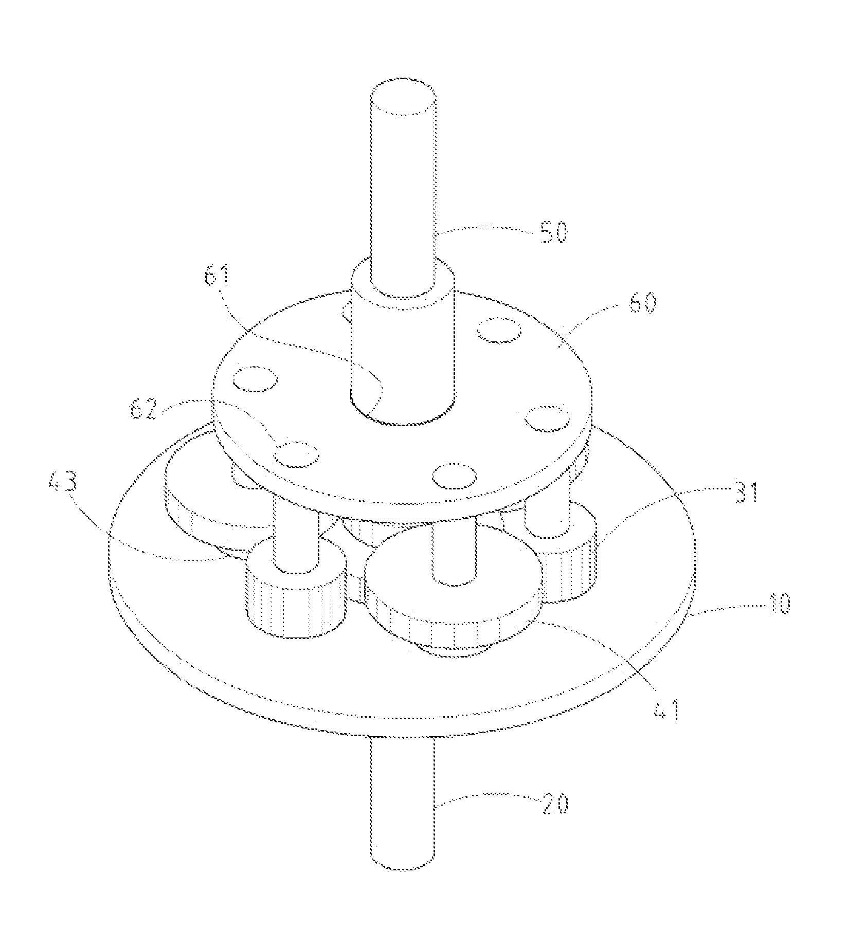
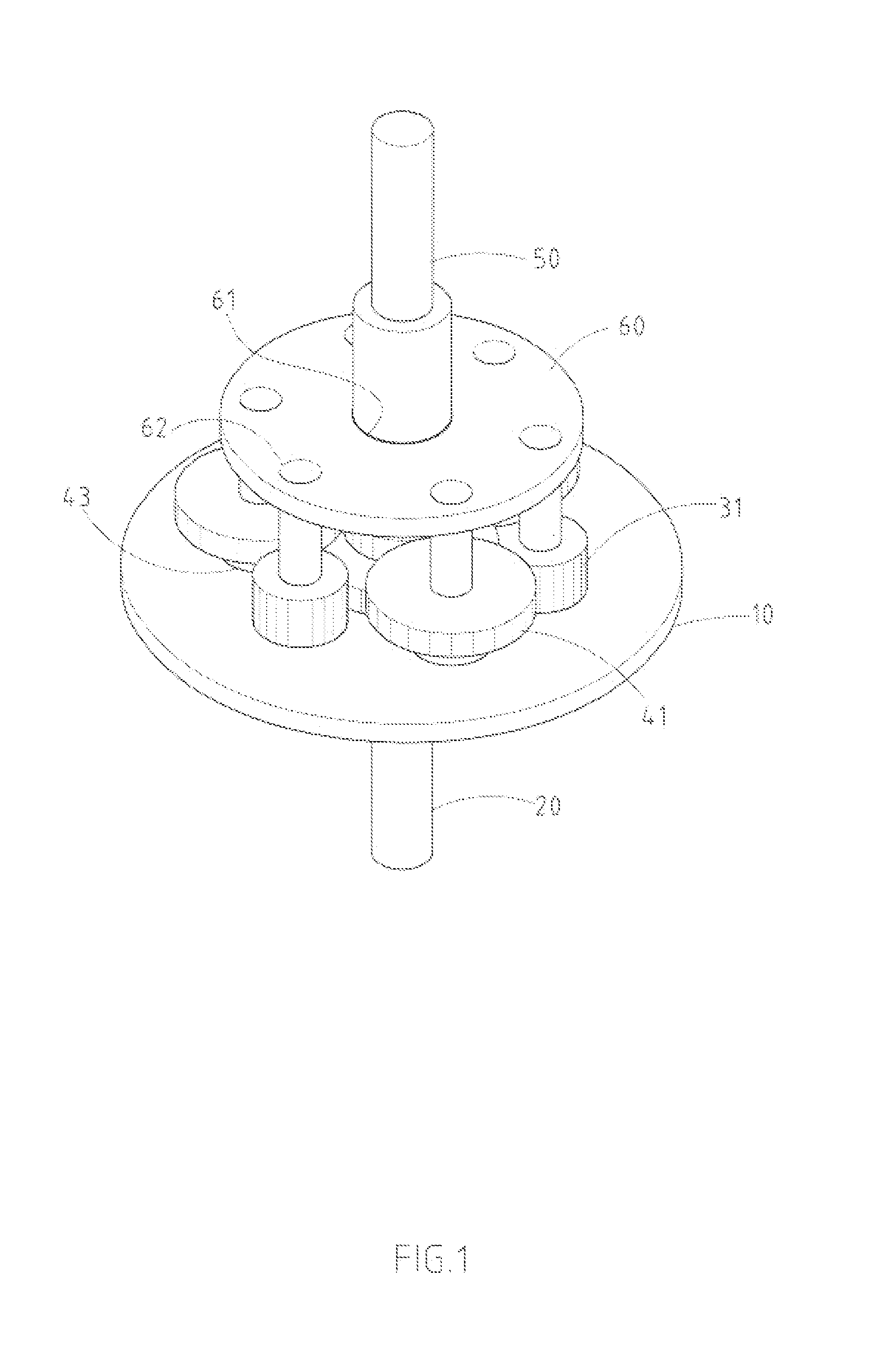
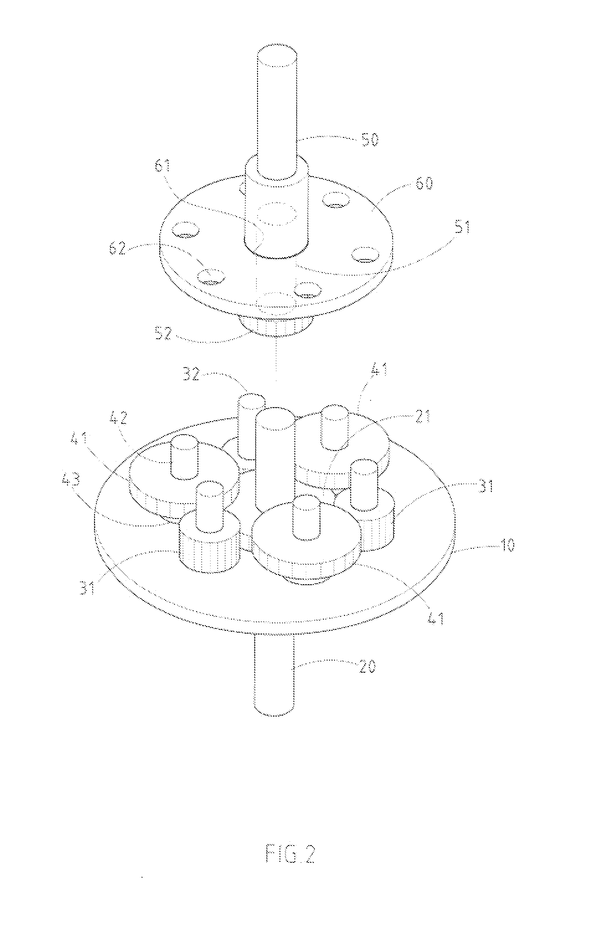
[0013]The features and the advantages of the present invention will be more readily understood upon a thoughtful deliberation of the following detailed description of a preferred embodiment of the present invention with reference to the accompanying drawings.

[0014]As shown in FIGS. 1–5, a differential device embodied in the present invention comprises: a flywheel 10, which has a center hole 11; a main shaft 20, which penetrates the center hole 11 of the flywheel 10 and whose inner and outer ends stretch on both sides the flywheel 10; and a main central gear 21, which is integrated in the inside of the main shaft 20.

[0015]The invention also has a main train of planet gears 30, which consists of several gears 31, each of which is positioned around and connected with the main flywheel 10 at the same axis direction at intervals by jack post 32. The off-center side of each gear 31 is geared up with the main central gear 21 to transmit drive.

[0016]There is a secondary train of planet gear...


PUM


Abstract

A differential device includes a main flywheel, a main shaft integrated with the main central gear, prime train of planet gears, secondary train of planet gears, secondary shaft integrated with the secondary central gear, and a fixing plate. This improved device can resolve problems of current bevel gear-driven differential devices and improve dramatically the drive force and stability of the differential device.

Description

RELATED U.S. APPLICATIONS[0001]Not applicable.STATEMENT REGARDING FEDERALLY SPONSORED RESEARCH OR DEVELOPMENT[0002]Not applicable.REFERENCE TO MICROFICHE APPENDIX[0003]Not applicable.FIELD OF THE INVENTION[0004]The present invention relates generally to a differential device, and more particularly to a device comprising a main flywheel, a main shaft integrated with the main central gear, prime train of planet gears, secondary train of planet gears, secondary shaft integrated with the secondary central gear, and a fixing plate. The device can be used in transmission systems.BACKGROUND OF THE INVENTION[0005]A differential device, also known as a differential gear, is commonly used on the transmission mechanism of automobile tires. Since the distance traveled by the left and rights tires when the automobile is making a turn is different, the number of revolution cycles is different too. Herein, a differential device is employed to rotate the left and rights tires in opposite directions...

Claims


Application Information

Patent Timeline
Patent Type & Authority Patents(United States)
IPC IPC(8): F16H48/06
CPCF16H48/10F16H48/11F16H2048/106
Inventor LU, TAI-YANG
Owner TAIWAN JET POWER INDAL
Why Eureka
Try Eureka