Method for improving isolation of an antenna mounted on a structure

a technology for antennas and structures, applied in the field of antennas, can solve the problems of less reliable deployment mechanism of support structures, significant mechanical and electrical problems that need to be solved, and mounted on rather expensive deployable support structures, so as to reduce the scattering effect of surrounding structures, reduce the effect of deterioration of antenna signals, and facilitate the design of antennas and their deployable supporting structures

Active Publication Date: 2006-11-21
MACDONALD DETTWILER & ASSOC INC
View PDF5 Cites 2 Cited by
  • Summary
  • Abstract
  • Description
  • Claims
  • Application Information

AI Technical Summary

Benefits of technology

[0009]An advantage of the present invention is that the method uses the structure body it is mounted on as a physical barrier to at least partially isolate the global coverage antenna from the surrounding equipment, especially to at least partially isolate a receive antenna from a transmit antenna by having the structure located there between.
[0010]Another advantage of the present invention is that the method position of the antenna relative to the structure body allows a relatively low level of the scattering effect of the surrounding structure and equipment on the antenna signal.
[0011]A further advantage of the present invention is that the method allows the antenna to be positioned relatively close to the structure body so as to ease the design of the antenna and its deployable supporting structure, while minimizing the effects on the deterioration of the antenna signal.
[0012]Still another advantage of the present invention is that the method reduces the complexity of any deployment mechanism while increasing the overall reliability of the antenna.
[0013]Another advantage of the present invention is that the method allows the antenna support structure deployment mechanism to be located far from any other sensitive equipment mounted on the structure body so as to minimize the risk of interference therewith.
[0014]According to an aspect of the present invention, there is provided a method for improving the isolation of a wide coverage antenna mounted on a structure, the structure having a body, said body defining a first end wall perpendicular to a body axis and a peripheral wall surrounding said body axis, said first end wall defining a first external wall surface, said peripheral wall defining a peripheral external wall surface, said antenna having a generally elongated antenna body mounted on and extending from an antenna base along an antenna pointing axis, said antenna base pivotally mounting on the peripheral wall about a mounting axis parallel to and spaced apart from the structure body axis, said antenna being oriented in a direction pointing generally outwardly from said first wall surface with said antenna axis being generally parallel to and spaced apart from said mounting axis and the structure body axis, said method comprises the step of:

Problems solved by technology

Accordingly, significant mechanical and electrical problems need to be solved; especially when considering the complex and stringent mechanical and electrical environments the antennas encounter or need to survive.
Accordingly, they are usually mounted on rather expensive deployable support structure including hinges or the like.
The more hinges are used, the less reliable the support structure deployment mechanism is, and the more expensive it is, both design and manufacturing wise.
Similarly, the larger the antennas are, the more likely they have to include antenna deployment mechanisms, which is not a preferred design approach.

Method used


Image

  • Method for improving isolation of an antenna mounted on a structure
  • Method for improving isolation of an antenna mounted on a structure
  • Method for improving isolation of an antenna mounted on a structure

Examples


Embodiment Construction

[0041]With reference to the annexed drawings the preferred embodiments of the present invention will be herein described for indicative purpose and by no means as of limitation.

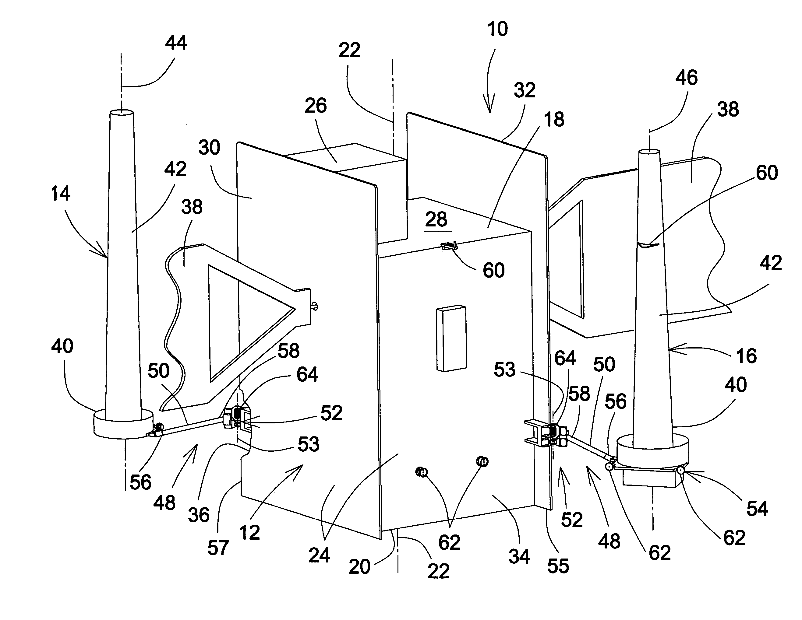
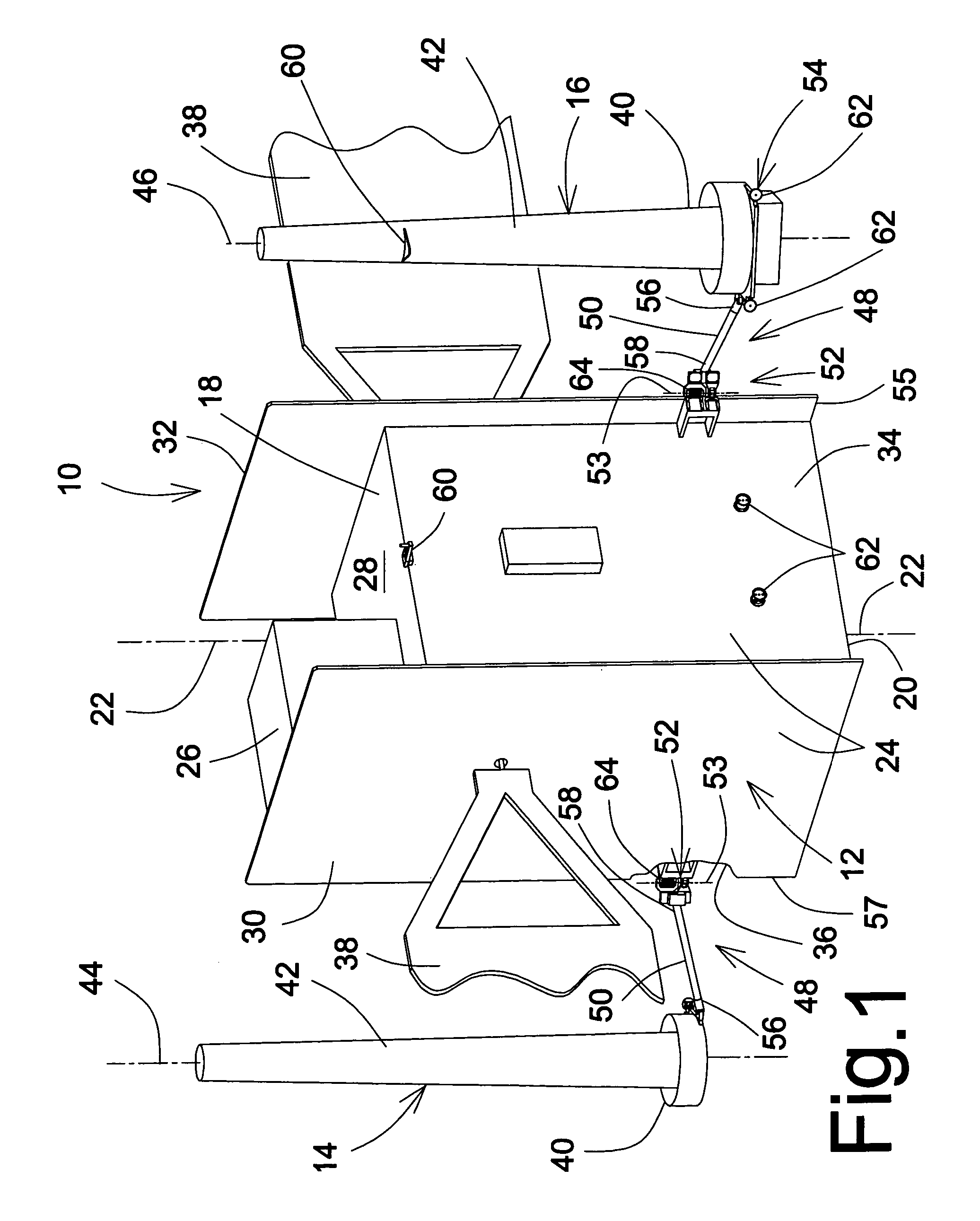
[0042]Referring to FIG. 1, there is schematically shown a spacecraft structure 10 which defines a generally elongated body 12 with a receive (Rx) antenna 14 and a transmit (Tx) antenna 16 mounted thereon. Both the Rx and Tx antennas 14, 16 are typically wide coverage antennas, most conventionally called global or earth coverage antennas. Any other type of antennas, such as omni-directional antennas or the like, could also be considered without departing from the scope of the present invention, as it would be obvious to one skilled in the art.

[0043]The spacecraft structure body 12 defines generally opposed first and second longitudinal end walls 18, 20 and a body axis 22. The body 12 further defines a peripheral wall 24 generally extending between the first and second end walls 18, 20.

[0044]The first end wall ...


PUM


Abstract

A method for improving the electric isolation of a wide coverage antenna mounted on a structure. The structure defines a peripheral wall and a first end wall and the elongated antenna has a base. The antenna pivotally mounts on the structure about a mounting axis parallel to the structure axis, in a spaced apart relationship relative to the peripheral wall in a direction pointing generally outwardly therefrom with the antenna base and at least part of an antenna body being in a step back relationship relative to the first end wall such that the antenna is at least partially electrically isolated by the structure while being substantially hidden from the first end wall. A second antenna similarly pivotally positioned relative to the peripheral wall can be generally opposed to the first antenna about the structure such that the two antennas are at least partially electrically isolated from one another.

Description

CROSS REFERENCE TO RELATED APPLICATIONS[0001]Benefit of U.S. Provisional Application for Patent Ser. No. 60 / 436,626, filed on Dec. 30, 2002, is hereby claimed.FIELD OF THE INVENTION[0002]The present invention relates to the field of antennas and is more particularly concerned with a method for improving the electric isolation of an antenna by its mounting position on a structure, and the relatively positioned antenna itself.BACKGROUND OF THE INVENTION[0003]It is well known in the art to use antennas mounted on a structure to allow communication with equipment located at a distance away. More specifically in the aerospace industry, global coverage antennas, including omni-directional antennas, are conventionally mounted on spacecraft structure to allow specific communications to and from the ground through a ground station on Earth. Accordingly, spacecraft mounted global coverage antennas are usually located on the conventionally called earth facing panel of the spacecraft to improve...

Claims


Application Information

Patent Timeline
Patent Type & Authority Patents(United States)
IPC IPC(8): H01Q1/12H01Q21/00H01Q3/02H01Q1/28H01Q1/52
CPCH01Q1/288H01Q1/52H01Q1/521H01Q1/525
Inventor GAUDETTE, YVESBRAND, YAN
Owner MACDONALD DETTWILER & ASSOC INC
Why Eureka
Try Eureka