Light irradiation device and inkjet printer

a technology of light irradiation and inkjet printer, which is applied in the direction of printing, point-like light sources, light sources, etc., can solve the problems of high temperature of substrate, difficult to further increase the radiance of long-arc lamps, and high temperature of substrates, so as to achieve strong light irradiation regions, regulate length, and high irradiance

Inactive Publication Date: 2011-05-03
USHIO DENKI KK
View PDF8 Cites 5 Cited by
  • Summary
  • Abstract
  • Description
  • Claims
  • Application Information

AI Technical Summary

Benefits of technology

[0036]The present invention was made on the basis of the situation described above, and has as a primary object to provide a light irradiation device that irradiates linearly focused light, that can yield high peak irradiance, and that has good uniformity of irradiance in the lengthwise direction of linearly focused light.
[0037]This invention has the further object of providing an inkjet printer that includes the light irradiation device described above, that can cure ink and other liquid materials with high efficiency, that consequently can reliably form patterns, such as images and circuits, with high graphic quality, and that has a low level of thermal effects on the substrate.

Problems solved by technology

However, even when irradiating with light focused from light source lamps using optical elements such as lenses and mirrors, the peak irradiance yielded will be limited unless the radiance of the light source lamps themselves is increased; this is the case even when using the microwave UV lamps as described in JP Pre-grant Patent Publication No. 2005-246955 and corresponding U.S. Patent Publication No. 2005 / 0168509.
However, the reality is that it is technically difficult to further increase the radiance of long-arc lamps, which have large light-emitting tubes, or microwave UV lamps.
Further, there are also the following problems in the inkjet printers described above.
Materials that are easily deformed by heat—paper, resin, or film, for example—are often used as the substrate 5, so if one simply uses lamps with higher power to increase the radiance, the effect on the substrate 5 of heat from light in the visible and infrared regions and from thermal radiation will be even greater, the temperature of the substrate will raise even higher, and this will be the source of degraded printing quality as such results in deformation.
However, putting such a reflecting mirror in place lengthens the optical path from the discharge lamp to the substrate by that much more; in the case of a long-arc type discharge lamp, for example, that makes it impossible to focus light in the lengthwise direction of the discharge lamp, and so the area irradiated by the light (the light irradiation region) is expanded, reducing the efficiency of light use and also making it impossible to obtain high enough irradiance in the light irradiation surface (the substrate surface).
As stated above, the reality is that it is difficult to increase the peak irradiance in the light irradiation surface beyond the conventional level and devise improvement of the ink curing process in inkjet printers that use the light-cure inkjet method.
In the light irradiation device described above, however, no particular consideration was given to the uniformity of irradiance in the lengthwise direction of the linearly focused light.
Poor uniformity of irradiance results in the problem that uniform processing across the full irradiation region is not possible.

Method used


Image

  • Light irradiation device and inkjet printer
  • Light irradiation device and inkjet printer
  • Light irradiation device and inkjet printer

Examples


first embodiment

Variation of First Embodiment

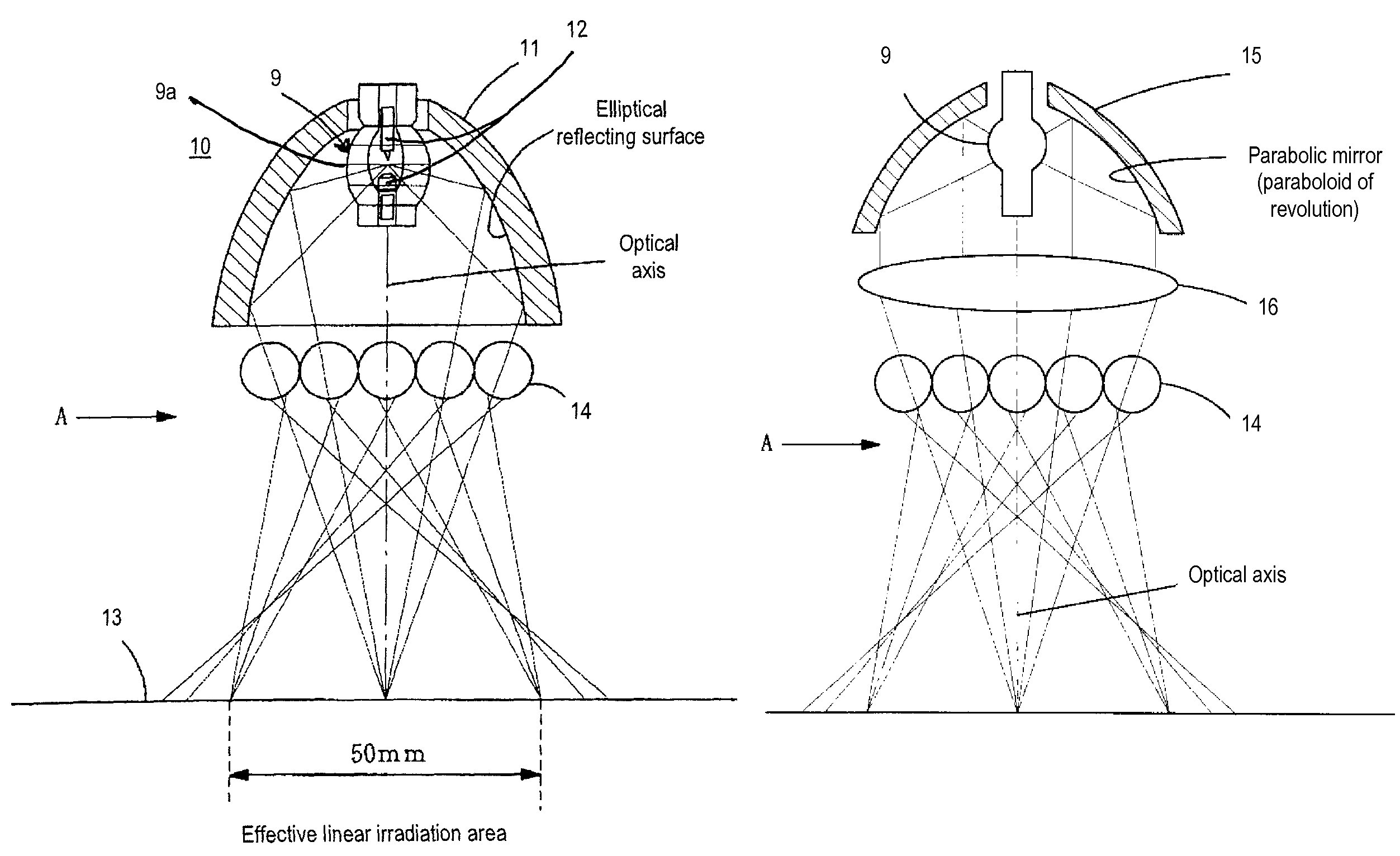
[0090]Now, in this embodiment, a reflector with a reflective surface in the shape of an ellipsoid of revolution is used as the means of focusing the light emitted from the lamp, but it is possible to replace this, as shown in FIGS. 3(a) &3(b), with a reflector 15 having a reflective surface in the shape of a paraboloid of revolution and a convex lens 16 on the light-emission side of the reflector 15. FIG. 3(a) is a diagram as seen from the radial direction of the rod lenses; FIG. 3(b) is a diagram as seen from the direction A in FIG. 3(a).

[0091]In FIG. 3, the reflector 15 is constituted by a parabolic mirror of which the reflective surface is a paraboloid of revolution centered on the beam axis, and the light-emitting portion (spot of the arc) of a short-arc type discharge lamp 9 is positioned at the its focal point.

[0092]The light from this discharge lamp 9 is reflected by the reflector 15 that surrounds the lamp 9, and gives collimated light. A convex ...

second embodiment

[0106]FIG. 6 is a diagram showing the second embodiment of this invention, which is constituted to obtain a longer linear light irradiation region. In FIG. 6, two of the light sources 10 shown in FIG. 1 are used in order to provide a long, linear light irradiation region, but it is also possible to use two of the light irradiation devices shown in FIG. 3.

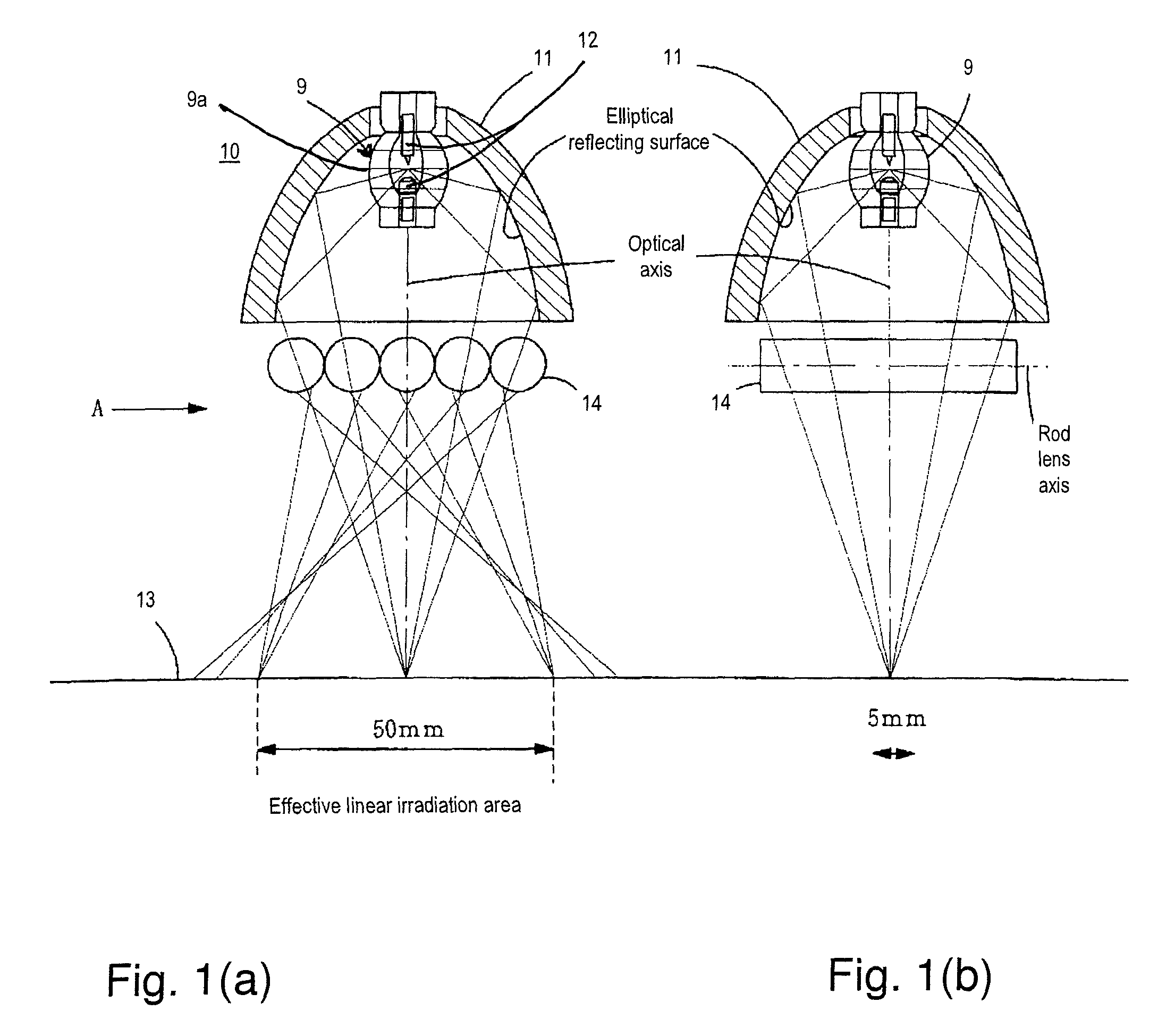
[0107]In FIG. 6, the light sources 101, 102 have the same configuration as the light source 10 shown in FIG. 1: a straight line connecting the pair of electrodes on an extension of the optical axis of the reflector 11, and the reflector 11 has a reflective surface that is an ellipsoid of revolution centered on that optical axis, with the light-emitting part of the discharge lamp 9 (the spot of the arc, for example) positioned at the first focal point of the reflector 11 that has a reflective surface that is an ellipsoid of revolution.

[0108]In the light sources 101, 102, light from the discharge lamp 9 is reflected by the reflector 1...

third embodiment

[0119]FIGS. 8(a)-8(c) are diagrams showing the third embodiment of the invention. This embodiment has reflecting mirrors 17 arranged parallel to the axial direction of the rod lenses 14 (lengthwise), i.e., on both sides of the rod lenses 14 in the embodiment shown in FIG. 1.

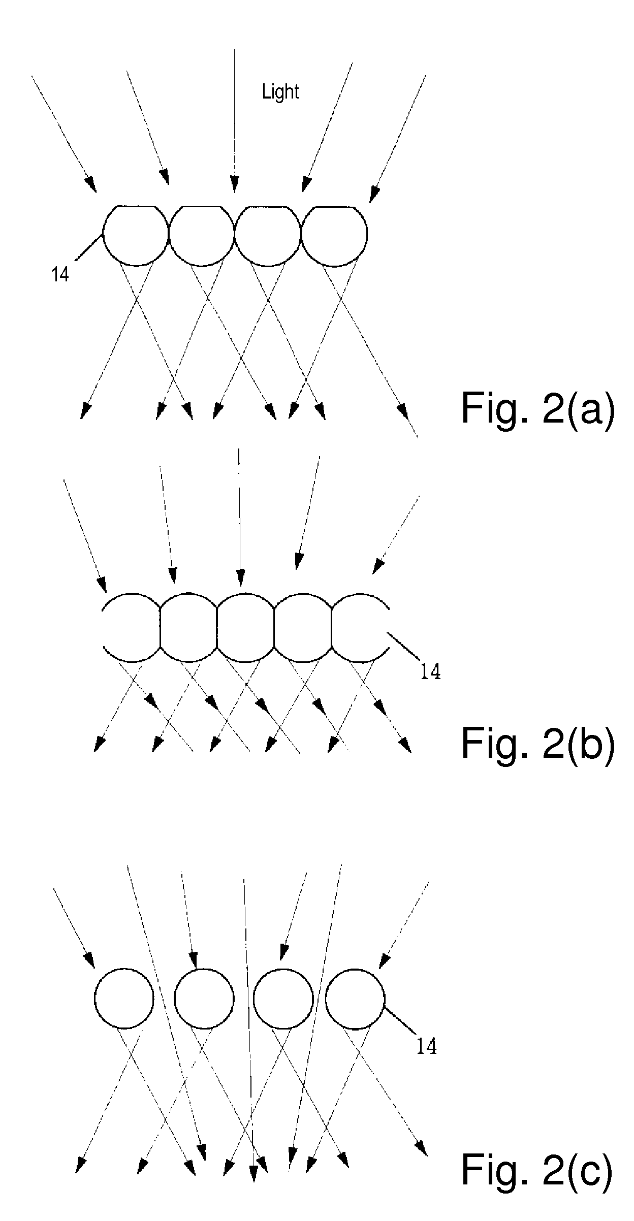
[0120]Of the light incident in the rod lenses 14, the light that is perpendicular to the axial direction (lengthwise) is spread by the rod lenses 14 after it is focused, as stated previously. For that reason, the irradiance peak of the light emitted from each rod lens 14 shifts and the light overlaps on the light irradiation surface; the irradiance distribution becomes uniform, but there is a irradiance distribution with higher irradiance at the center and lower irradiance at the edges.

[0121]In this embodiment, therefore, there are reflecting mirrors 17 on both sides of the light-emission side of multiple rod lenses 14, to reflect the spreading light in the direction perpendicular to the axial direction of the ro...


PUM


Abstract

A light irradiation device that is capable of good irradiance uniformity in the lengthwise direction and that is applicable to an inkjet printer. A light-emitting portion of a short-arc type discharge lamp is positioned at the first focal point of a reflector that has a reflecting surface in the shape of an ellipsoid of revolution, and the light from the discharge lamp is reflected by the reflector and is focused at the second focal point; after which the light is incident on multiple, columnar rod lenses 14. Of the light that is incident on the rod lenses, the light along the axial direction is focused at the second focal point of an elliptical reflector without being affected by the rod lenses, and the light along the direction perpendicular to the axial direction is focused by the rod lenses and then spreads and irradiates the light irradiation surface.

Description

BACKGROUND OF THE INVENTION[0001]1. Field of the Invention[0002]This invention concerns a light irradiation device that uses a short-arc lamp to form a linear, long thin light irradiation region and an inkjet printer. In particular, the invention relates to a light irradiation device that forms a linear light irradiation region having a uniform irradiance on the article to be irradiated, and an inkjet printer, in which this light irradiation device is mounted, that records images or circuits and other patterns on a substrate by ejecting a light-curable liquid material onto the substrate.[0003]2. Description of Related Art[0004]Because it is possible to produce images more conveniently and cheaply than the gravure method, in recent years, the inkjet printing method has been adopted in a variety of printing fields including specialty printing, such as photographs, printing of various kinds, marking, and color filters.[0005]In the inkjet printing method, it is possible to obtain high g...

Claims


Application Information

Patent Timeline
Patent Type & Authority Patents(United States)
IPC IPC(8): B41J2/14B41J2/16F21Y101/00
CPCB41J11/002B41J11/0021B41J11/00214B41J2/01B41J2/44
Inventor NAKATA, SHIGENORIWATANABE, KATSUYA
Owner USHIO DENKI KK
Why Eureka
Try Eureka