Light irradiation apparatus and injet printer

a technology of light irradiation and inkjet printer, which is applied in the direction of mirrors, printing, instruments, etc., can solve the problems of reducing the peak irradiance ra

Inactive Publication Date: 2011-06-21
USHIO DENKI KK
View PDF36 Cites 6 Cited by
  • Summary
  • Abstract
  • Description
  • Claims
  • Application Information

AI Technical Summary

Benefits of technology

[0033]The invention was devised to eliminate the above described disadvantages in the prior art. Thus, a primary object of the invention is to devise a light irradiation apparatus in which high peak irradiance can be obtained while the amount of heat influence on the article which is to be irradiated with light can be reduced.
[0034]Another object of the invention is to devise an inkjet printer which has the above described light irradiation apparatus in which setting treatment of the ink can be achieved with high efficiency, so that pictures can reliably be made with high image quality while the amount of heat influence on the recording medium is low.
[0051]With the light irradiation apparatus in accordance with the invention, by using a discharge lamp of the short arc type as the light source lamp and by arranging an optical system with a certain reflection component, the light from the discharge lamp of the short arc type which forms a point light source in each direction of the light irradiation surface can be focused to extend linearly by the broadening of the light irradiation region on the recording medium according to the increase of the length of the optical path being suppressed. Therefore, the light from the discharge lamp can be used with high efficiency. Moreover, since the radiance of the discharge lamp is inherently high, a high peak irradiance can be obtained on the area to be irradiated.
[0052]Furthermore, by the arrangement in which the light from the light source lamp is reflected by the reflection component and thus emerges, direct incidence of the light from the visible range to the IR range which is contained in the radiant light from the discharge lamp, and direct incidence of the radiant heat in the course of discharge lamp operation onto the article to be irradiated with light are prevented in the case in which for example light in the UV range emerges. Thus, the amount of heat influence on the article to be irradiated with light can be reduced.
[0053]By the inkjet printer with the above described light irradiation apparatus, ink of the photosetting type which has been applied to the recording medium is irradiated with light from the discharge lamp with high irradiance so that the ink can set (photopolymerize) immediately after application to the recording medium with high efficiency. In this way, the time necessary for setting can be reduced, and as a result, changing of the dot form can be prevented. Therefore, pictures with high image quality can be reliably formed. Furthermore, especially since, for an inkjet printer using ink of the UV radiation setting type, the light from the discharge lamp is reflected and thus the recording medium is irradiated, the light from the IR range to the visible range contained in the radiant light from the discharge lamp which is unnecessary for setting of the ink, and the radiant heat in the course of operation of the discharge lamp can be prevented from being directly incident on the recording medium. Therefore, the amount of heat influence on the recording medium can be reduced and deformation of the recording medium can be prevented.
[0054]In accordance with the invention, the light irradiation apparatus (lamp housing) can be produced that is smaller and lighter than one with a discharge lamp of the long arc type. Therefore, the weight of the entire inkjet printer can be reduced, and moreover, the printing speed can be increased by increasing the efficiency of the setting treatment of the ink.

Problems solved by technology

The longer the ink is exposed to the atmosphere, the lower the rate of setting and the greater the time consumption for ink setting.
When the ink has not immediately set (photopolymerized) after application of the ink to the recording medium, due to the frequent changes of the dot form of the applied ink, a picture with high image quality can no longer be obtained.
Even if using optical elements, such as lenses, mirrors and the like, the light from the light source lamp is focused and thus irradiated, there is a limit to the magnitude of the peak irradiance that can be obtained since the radiance of the light source lamp, itself, has not been increased.
However, in reality, it is technically difficult to further increase the radiance of a lamp of the long arc type and a microwave UV lamp that has light emitting parts which are large.
The recording medium R is thus shifted into a still higher temperature state, by which there are the disadvantages that deformations and the like often arise and it becomes difficult to form pictures with high image quality.
However, in the case of an arrangement of such a reflection mirror, the length of the optical path between the discharge lamp and the recording medium is increased by which, for example, focusing is impossible in the case of a discharge lamp of the long arc type with respect to the lengthwise direction of the discharge lamp.
As was described above, in reality, for an inkjet printer using the inkjet method of the photosetting type, an improvement of the setting treatment of the ink could not be achieved by using an inkjet printer with high radiance of the light source lamp in itself, and thus, an increase of the peak irradiance on the irradiated surface could not be achieved.

Method used


Image

  • Light irradiation apparatus and injet printer
  • Light irradiation apparatus and injet printer
  • Light irradiation apparatus and injet printer

Examples


first embodiment

[0069]The light irradiation apparatus according to the first embodiment of the invention comprises the following:[0070]a discharge lamp of the short arc type;[0071]at least one light source part having a reflector which reflects light from the discharge lamp; and[0072]a reflection mirror which reflects the light radiated from the light source part and allows it to emerge.

In this connection, the light from the discharge lamp is focused and emitted by a reflection component which is comprised of the reflector and the reflection mirror, such that a linearly extending light irradiation region is formed on the surface to be irradiated.

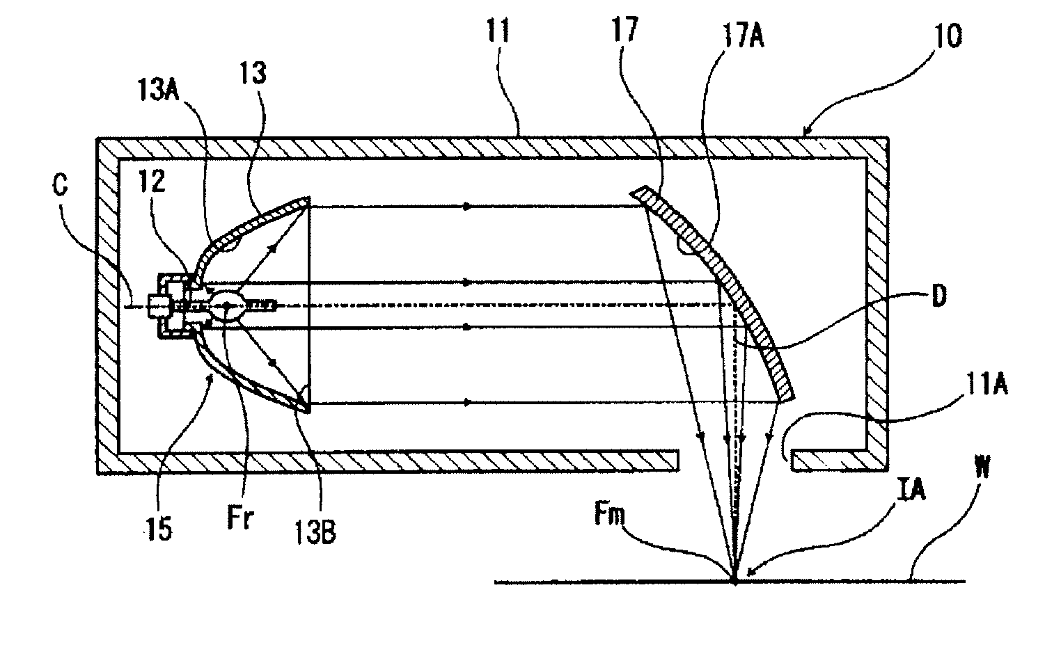
[0073]FIG. 1 is a schematic cross-sectional view of the arrangement of important parts of one example of a first embodiment of the light irradiation apparatus in accordance with the invention. This light irradiation apparatus 10 has an outside cover 11 that is, for example, box-shaped and which has a light exit opening 11A which is open in one direction (to...

second embodiment

[0079]The light irradiation apparatus according to the second embodiment of the invention has a discharge lamp of the short arc type and at least one light source part of a reflector which reflects the light from this discharge lamp. A reflection component of at least the reflector focuses and emits the light from the discharge lamp such that a linearly extending light irradiation region is formed on the surface to be irradiated.

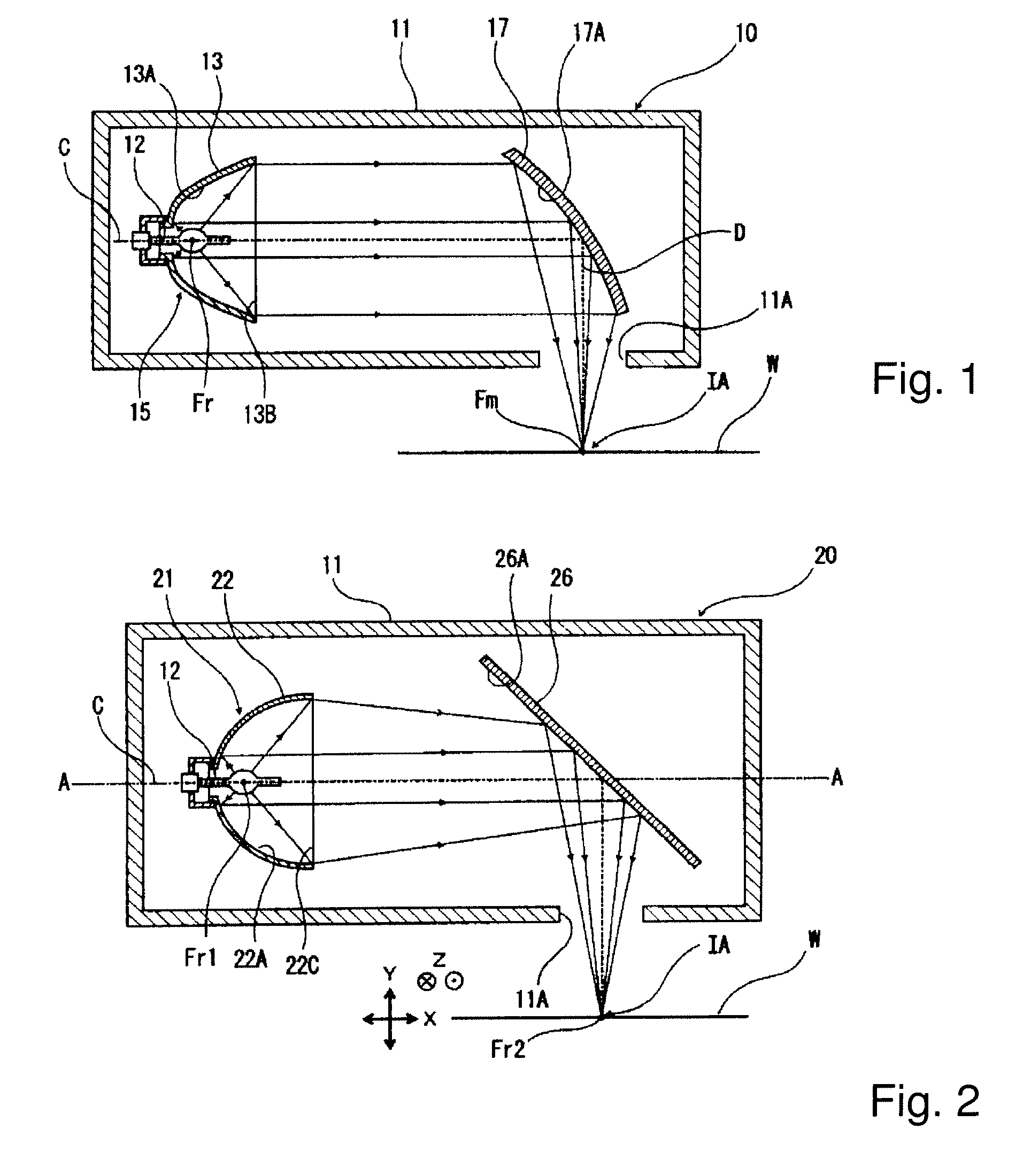
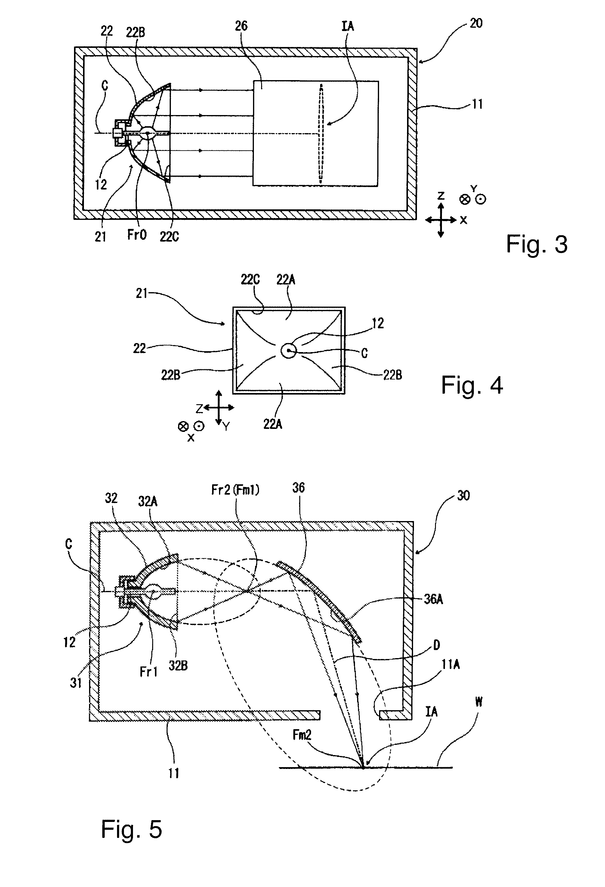
[0080]FIG. 2 shows a schematic cross section of the arrangement of important parts of one example of the second embodiment of the light irradiation apparatus in accordance with the invention. FIG. 3 is a partial cross section taken along line A-A in FIG. 2, which is along a plane in the light irradiation apparatus 20 which runs parallel to the light irradiation surface W.

[0081]This light irradiation apparatus 20 has the same basic arrangement as the light irradiation apparatus 10 according to the above described first embodiment. In the outer cover 11 with a...

third embodiment

[0091]The light irradiation apparatus according to the third embodiment of the invention comprises a discharge lamp of the short arc type, at least one light source part of a reflector which reflects the light from this discharge lamp, and a reflection mirror which reflects the light emitted by the light source part and allows it to emerge. A component formed of the reflector and the reflection mirror focuses and emits the light from the discharge lamp such that a linearly extending light irradiation region is formed on the surface which is to be irradiated.

[0092]FIG. 5 shows a schematic cross section of the arrangement of important parts of one example of the third embodiment of the light irradiation apparatus in accordance with the invention. This light irradiation apparatus 30 has the same basic arrangement as the light irradiation apparatus 10 according to the above described first embodiment. In the outer cover 11 with a light exit opening 11A which is open in a single directio...


PUM


Abstract

A light irradiation apparatus in which high peak irradiance is obtained and the heat influence on the article being irradiated with light is reduced, and also an inkjet printer which has such a light irradiation apparatus in which pictures with high image quality can be reliably made and the amount of heat influence on the recording medium is low is achieved using a light irradiation apparatus having a discharge lamp of the short arc type and a reflection component for reflecting the light of this discharge lamp. The light of the discharge lamp is radiated in a state in which it is focused by the reflection component so as to extending linearly on the light irradiation area. The inkjet printer has a head part with the above described light irradiation apparatus, the light from which sets ink of the photosetting type which has been applied to the recording medium

Description

BACKGROUND OF THE INVENTION[0001]1. Field of the Invention[0002]The invention relates to a light irradiation apparatus and an inkjet printer. The invention relates especially to a light irradiation apparatus which forms a line-like, narrow light irradiation region on the article to be irradiated with light, and irradiates it with light, and to an inkjet printer in which such a light irradiation apparatus is installed and with which images are recorded on a recording medium.[0003]2. Description of the Prior Art[0004]Currently, for example, an inkjet recording method is used for various printing tasks such as reprinting, for example, photography printing, marking color filters and the like, because pictures can be made by an engraved printing method easily, and moreover, at low cost.[0005]In an inkjet printer using such an inkjet recording method, pictures with high image quality can be produced by a write head which regulates and delivers fine dots which are suitably combined with in...

Claims


Application Information

Patent Timeline
Patent Type & Authority Patents(United States)
IPC IPC(8): B41J2/01G02B5/10
CPCB41J11/002B41J11/00214B41J2/01B41J2/435B41J11/00218
Inventor NAKATA, SHIGENORINAMAI, MASAHITO
Owner USHIO DENKI KK
Why Eureka
Try Eureka