Sliding mechanism for optical compact disk drive

a technology of optical compact disk drive and sliding mechanism, which is applied in the direction of information storage, data recording, instruments, etc., can solve the problems of affecting the quality of the product and increasing production costs, and achieve the effects of reducing the gap between the slide tracks, reducing friction, and reducing the amount of slide tracks

Inactive Publication Date: 2006-11-21
MICRO-STAR INTERNATIONAL
View PDF6 Cites 18 Cited by
  • Summary
  • Abstract
  • Description
  • Claims
  • Application Information

AI Technical Summary

Benefits of technology

[0008]It is therefore an object of the invention to provide a sliding mechanism that can overcome the above disadvantages of the prior art. The sliding mechanism includes a right slide track 13 and a left slide track 13a respectively mounted at opposite sides of a tray 5 of a optical compact disk drive. A plurality of bulbous contacts 9 are respectively formed on the right and left slide tracks to fit retaining portions of a lower cover of the optical compact disk drive. By respectively placing the bulbous contacts against the corresponding retaining portions, the tray 5 moves forth and back in a stable manner with reduced friction. The amount of slide tracks is reduced and thus the gap between the slide tracks is also reduced. The tray 5 remains stable, even when being pulled out to an outmost position away from the optical compact disk drive and pushed in to its innermost position. When the tray 5 of the optical compact disk drive is pushed in to an innermost position inside the optical compact disk drive, the vibration caused by rotation of a shaft motor 3 is greatly reduced, which allows the optical compact disk drive to be operated under a stable condition. The hooks of the right and left slide tracks are designed to be hooked with the right rear bent portion and the left rear bent portion, which prevents any slipping of the tray 5.

Problems solved by technology

The dual-track sliding mechanism needs at least four tracks, which increases the production cost.
Therefore, the tray 5 may experience slight loosing during operation, which impacts the quality of the product.

Method used


Image

  • Sliding mechanism for optical compact disk drive
  • Sliding mechanism for optical compact disk drive
  • Sliding mechanism for optical compact disk drive

Examples


Embodiment Construction

[0034]Wherever possible in the following description, like reference numerals will refer to like elements and parts unless otherwise illustrated.

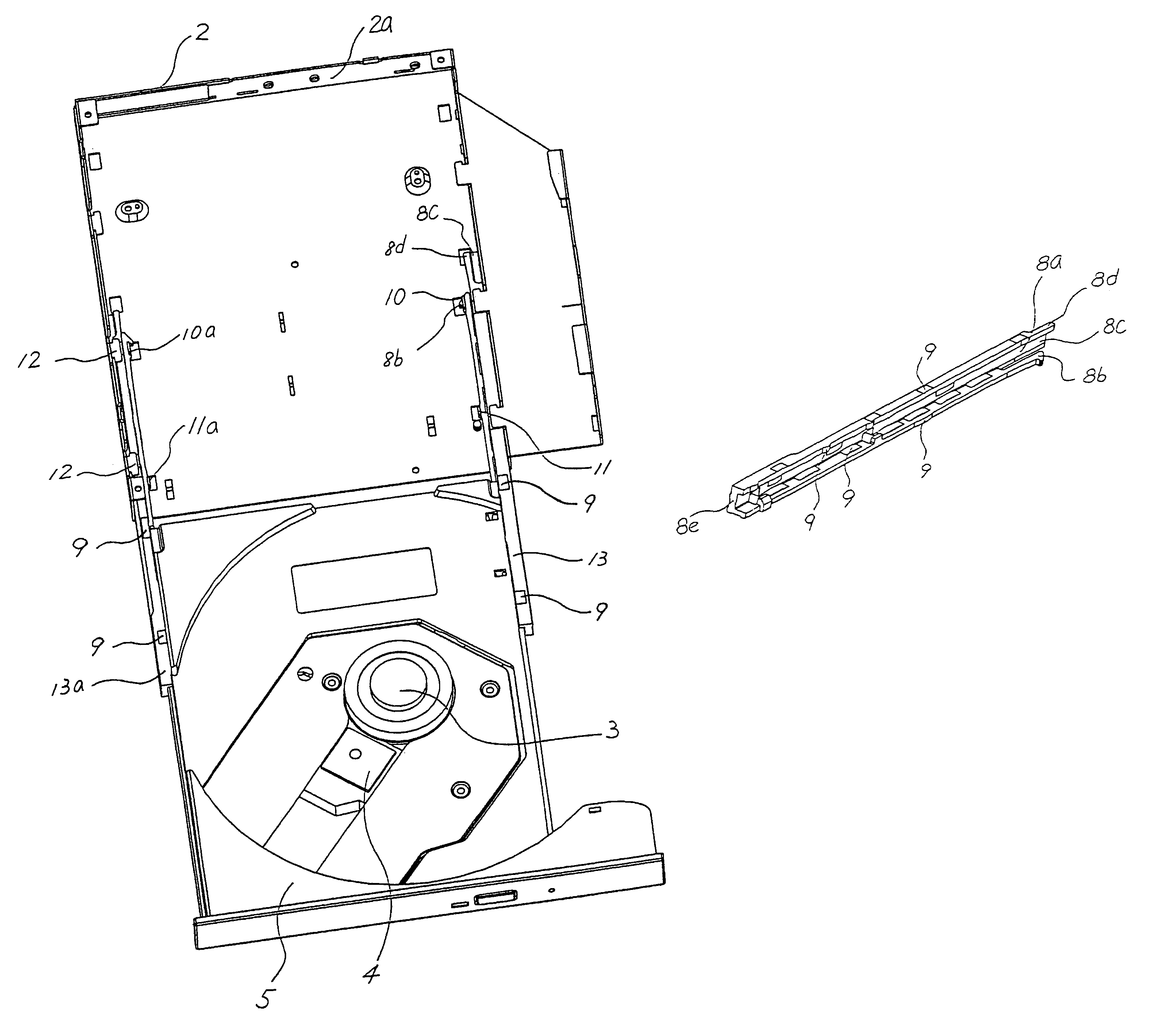
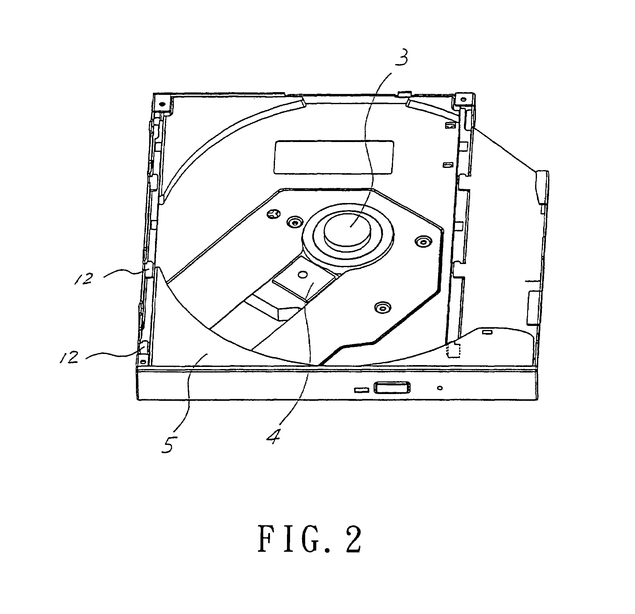
[0035]Referring to FIG. 2, the present invention provides a single-track sliding mechanism for an optical compact disk drive, including an upper cover 1, a lower cover 2, a tray 5, a right slide track 13 and a left slide track 13a. The right slide track 13 and the left slide track 13a are respectively mounted at either side of the tray 5. The tray 5 is slidably mounted between the upper cover 1 and the lower cover 2, and slides forward and backward along the right slide track 13 and the left slide track 13a.

[0036]FIG. 4A to FIG. 4E are schematic views of a left slide track 13a. FIG. 5A through FIG. 5C are schematic views of the right slide track 13. As illustrated, each of the right slide tracks 13 and left slide tracks 13a includes an extended track 8e and a slide body 8a. The slide body 8a provides a hook 8b, a protection piece 8c and a ...


PUM

PropertyMeasurementUnit
incline angleaaaaaaaaaa
L shapeaaaaaaaaaa
reverse L shapeaaaaaaaaaa

Abstract

A sliding mechanism for an optical compact disk drive includes right and left slide tracks respectively mounted at opposite sides of a tray of the optical compact disk drive. A plurality of bulbous contacts are formed on the right and left slide tracks respectively to fit with a plurality of retaining portions of a lower cover of the optical compact disk drive. By respectively having the bulbous contacts in point to point contact with the corresponding retaining portions, the tray smoothly moves in a stable manner between its outermost and innermost positions. A slide body of each slide track is provided with a hook, a protection piece and a fastening piece to hold the tray at its outermost or innermost positions. Thereby, the stability and effectiveness of the optical compact disk drive assembled with the sliding mechanism of the invention is increased.

Description

BACKGROUND OF THE INVENTION[0001]1. Field of the Invention[0002]The present invention relates to a sliding mechanism for an optical compact disk drive. More particularly, the present invention relates to a sliding mechanism that includes a pair of slide tracks respectively mounted at opposite sides of a tray of an optical compact disk drive. A plurality of bulbous contacts are respectively formed on the right and left slide tracks to fit retaining portions of a lower cover of the optical compact disk drive. By respectively having the bulbous contacts in point-to-point contact with the corresponding retaining portions, the tray moves forth and back with reduced frictions. A slide body is provided with a hook, a protection piece, and a fastening piece. The hook and fastening piece have an inclined angle inclined inwardly toward the shaft motor for firmly clamping the tray's outermost and innermost portions respectively. The stability of the optical compact disk drive assembled with th...

Claims


Application Information

Patent Timeline
Patent Type & Authority Patents(United States)
IPC IPC(8): G11B33/02G11B17/04
CPCG11B17/056G11B33/02
Inventor CHIOU, YAO JIAWU, JEN-CHEN
Owner MICRO-STAR INTERNATIONAL
Why Eureka
Try Eureka