Releasable skate retarder for railway cars

a technology for railway cars and retarders, which is applied in the direction of track brakes, railway components, transportation and packaging, etc., can solve the problems of increasing fuel costs, causing considerable wear and tear on the locomotive, and producing squeal noise, etc., and achieves the effect of quick and easy gap adjustmen

Inactive Publication Date: 2006-11-28
TRACKSIDE SERVICES
View PDF7 Cites 9 Cited by
  • Summary
  • Abstract
  • Description
  • Claims
  • Application Information

AI Technical Summary

Benefits of technology

[0007]In accordance with another aspect of the invention, the retarder provides for rapid and easy adjustment of the gap between the shoes and the running rails for compensating for wear of the shoes. In one embodiment, the rams are bidirectional devices, allowing the retarder to function also in a service mode in which the operating mechanism moves the shoe beams outwardly, allowing the insertion of shims. The presence of the shims causes the shoes to be repositioned closer to the running rails compensating for wear on the shoes.

Problems solved by technology

When a string of railway cars is being pulled through the retarder by a locomotive, considerable squeal noise is produced.
Moreover, the high resistance to motion afforded by the retarder to all of the railway cars in the string results in considerable wear and tear on the locomotive needed to pull the string of railway cars through the retarder.
Also, fuel costs are increased due to the energy required to pull a string of railway cars through the retarder.
A further limitation is that the friction rails are subject to wear and must be replaced periodically as they wear.
Moreover, pulling a string of railway cars through the retarder while the wheels of the railway cars are wedged between the riding rails and the friction rails can result in fatigue on the springs.
However, this requires loosening the bolts for each bracket and adjusting the hooks to change the wear plates.
This is a time consuming task considering the large number of spring pairs that employed.
For example, replacement of the wear plates can take two or more hours, and the cost for such maintenance can be considerable.
Moreover, during this results in considerable down time for the classification yard.

Method used


Image

  • Releasable skate retarder for railway cars
  • Releasable skate retarder for railway cars
  • Releasable skate retarder for railway cars

Examples


Embodiment Construction

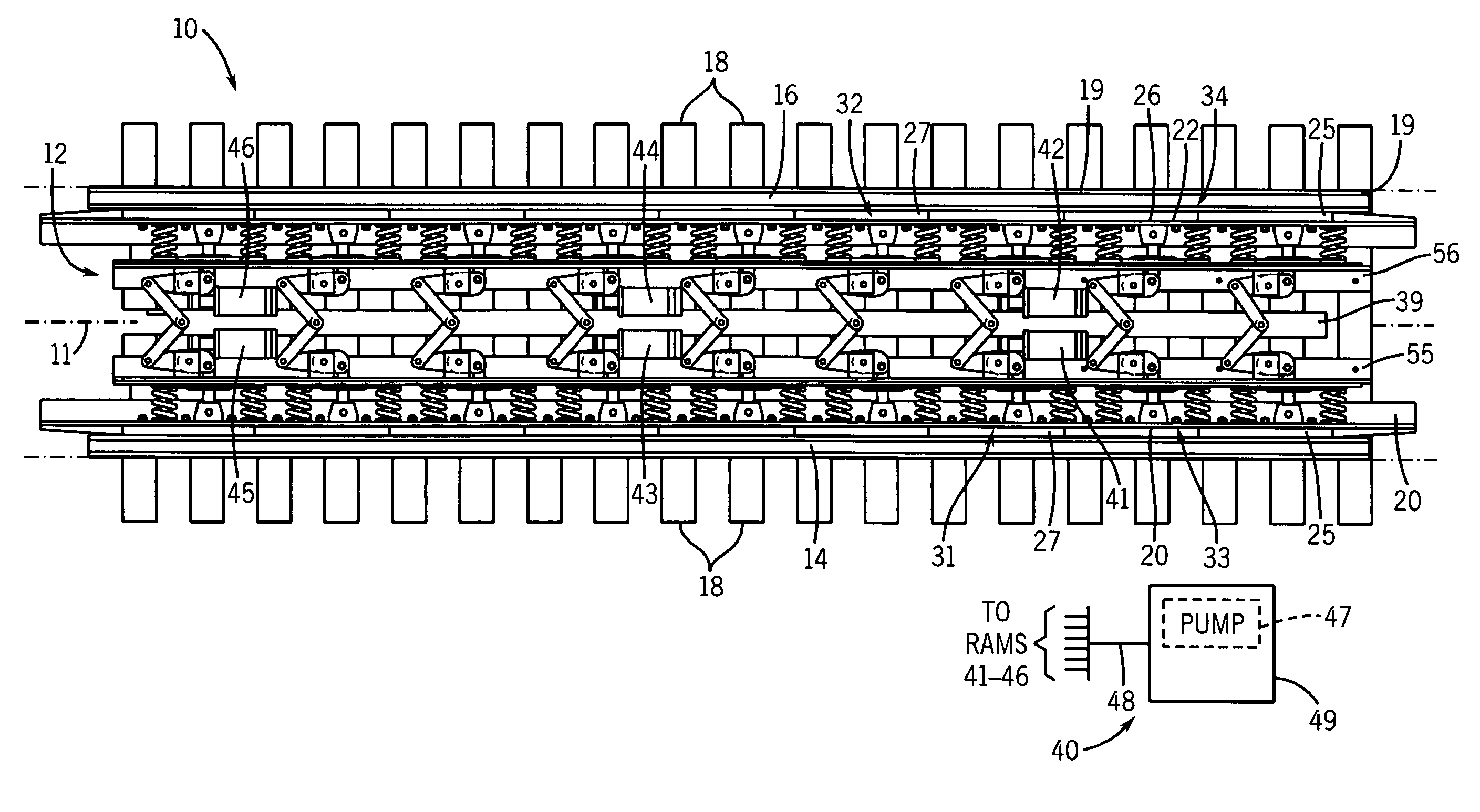
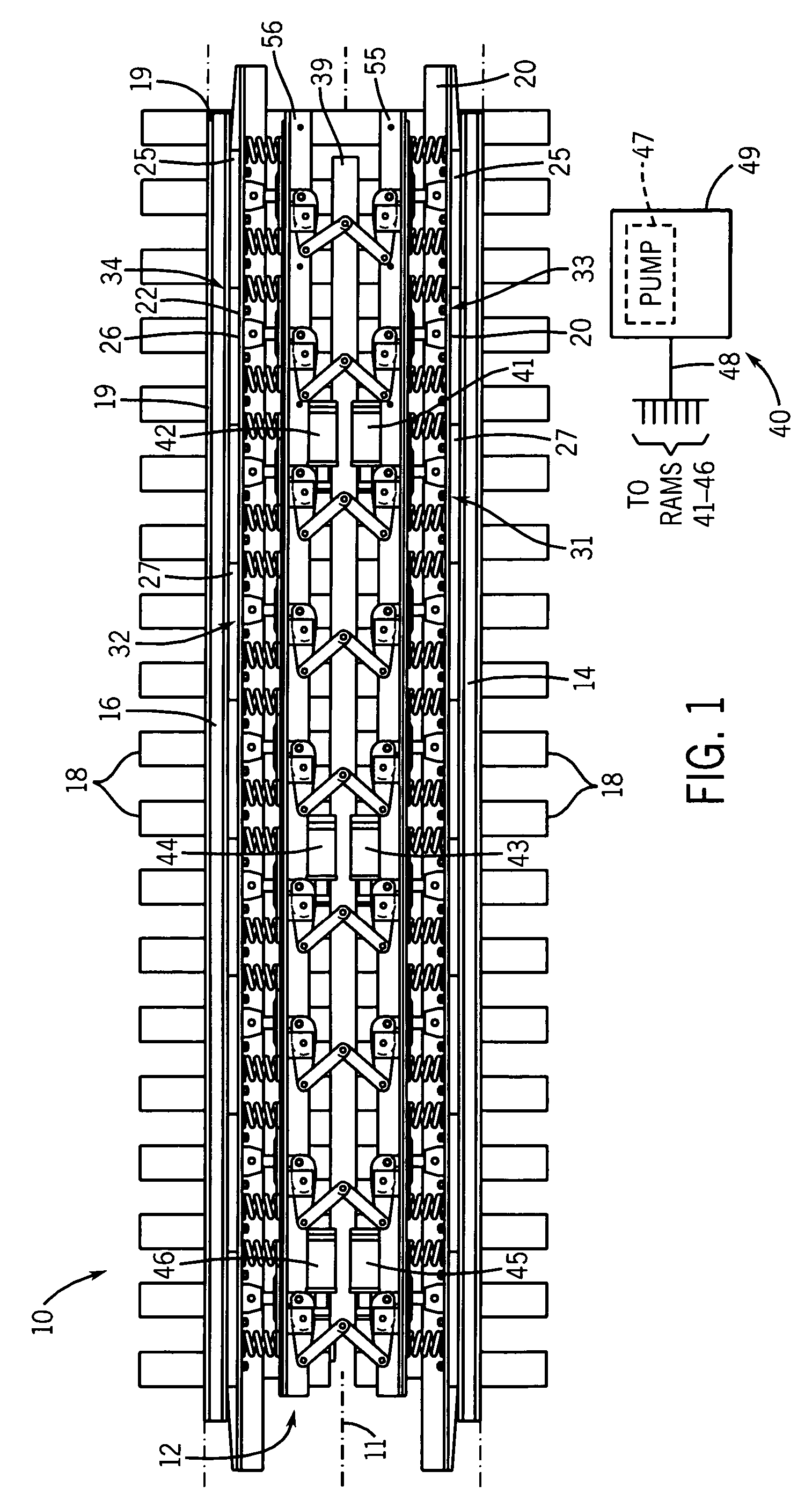
[0020]Referring to FIG. 1 of the drawings, there is shown a section of railway track 10 incorporating a railway car retarder 12 of the present invention. The railway track 10 includes a left running rail 14 and a right running rail 16 which are supported on ties 18 in the conventional manner. In one preferred embodiment, the retarder 12 is a skate retarder which is used in primarily for stopping the first railway car into a classification track and allowing other railway cars to couple to it while eliminating the possibility of the railway car running out of the retarder 12.

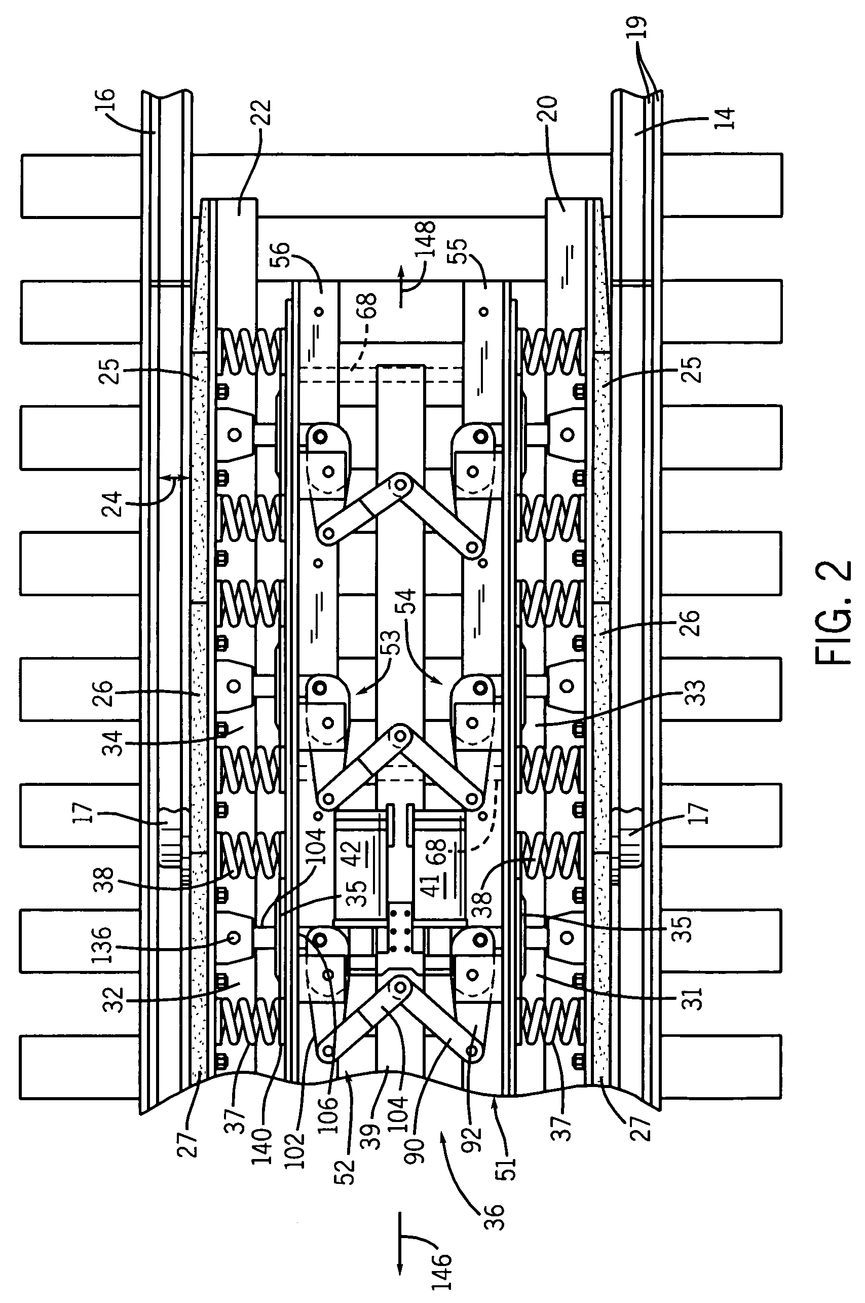
[0021]The retarder 12 includes a pair of shoe beams 20 and 22 which extend parallel to the running rails 14 and 16, near the insides of the running rails 14 and 16, respectively. The shoe beams 20 and 22 carry replaceable shoes, such as shoes 25, 26 and 27, preferably of steel. The shoes are engaged by the wheels of a railway car moving through the gap 28 between the running rails 14 and 16 and the shoe beams 20 ...


PUM


Abstract

The present invention provides a releasable skate retarder for railway cars. The retarder includes a plurality of spring packs including springs which bias shoe carrying beams toward running rails, trapping wheels of a railway car entering the retarder between the shoes and the running rails, and applying a frictional force to the railway car wheels for stopping the railway car and retaining the railway car in the retarder. The retarder is operable in a release mode in which an operating mechanism moves the shoe beams to a release position in which the spring force is released, allowing the railway car to move freely through the retarder. The retarder is operable in a service mode in which the operating mechanism moves the shoe beams outwardly, allowing the insertion of shims which cause the shoes to be repositioned closer to the running rails to compensate for shoe wear. In one embodiment, the operating mechanism includes a plurality of rams and a common operating member which couples the rams to the spring packs, for drawing the shoe beams inwardly when operating in the release mode and for pushing the spring packs outwardly when operating in the service mode.

Description

CROSS REFERENCE TO RELATED APPLICATIONS[0001]This application is a continuation of application Ser. No. 10 / 626,327, filed on Jul. 24, 2003 now U.S. Pat No. 6,829,998, which is a continuation of Ser. No. 09 / 949,053, filed on Sep. 7, 2001, now abandoned, which claims priority of provisional application No. 60 / 231,264, filed on Sep. 8, 2000.BACKGROUND OF THE INVENTION[0002]This invention relates to skate retarders for railway cars and, more particularly, to a releasable skate retarder including a wear adjustment mechanism.[0003]Fixed spring-loaded retarders are commonly employed in railway classification yards. The basic function of a fixed, spring-loaded retarder is to offer a preset resistance to all railway cars that are directed into the retarder. This is provided by devices that are installed in a section of railway track to retard or arrest the rolling movement of railway cars by pressing a friction rail against the wheels of the railway cars so that the railway cars are braked b...

Claims


Application Information

Patent Timeline
Patent Type & Authority Patents(United States)
IPC IPC(8): B61K7/02B61K7/00B61K7/08
CPCB61K7/08
Inventor KICKBUSH, GREGORY F.
Owner TRACKSIDE SERVICES
Why Eureka
Try Eureka