
Conduit overheating detection system

a detection system and conduit technology, applied in the direction of burners, breathing protection, combustion types, etc., can solve the problems of overheating, equipment or patient safety being compromised, and the condensation of water vapour occurring

Inactive Publication Date: 2006-11-28
FISHER & PAYKEL HEALTHCARE LTD
View PDF7 Cites 82 Cited by
  • Summary
  • Abstract
  • Description
  • Claims
  • Application Information

AI Technical Summary

Benefits of technology

[0005]It is an object of the present invention to provide a conduit overheating detection system for a respiratory conduit heating element, which goes some way towards overcoming the abovementioned disadvantages.
[0010]ii) if said current is outside a safe current region, then reduce the power supplied by said power supply means to said heating element so as to alter the current in said heating element to within said safe current region and prevent occurrence of said conduit and said heating element overheating, then
[0020]ii) if said current is outside a safe current region, then reduce the power supplied by said power supply means to said gases transportation pathway heating means so as to alter the current in said gases transportation pathway heating means to within said safe current region and prevent occurrence of said conduit and said heating element overheating, then
[0028]iii) if said current approaches a predetermined limit, then reduce the power supplied by said power supply means to said heating element so as to alter the current in said heating element to retreat from said predetermined limit and prevent occurrence of said conduit and said heating element overheating, then

Problems solved by technology

In such a case where the gases have been humidified, and therefore laden with water, it is likely that during transport through a conduit to the patient, condensation of that water vapour will occur.
This over-heating may occur under no-flow circumstances, or if excessive insulation such as a blanket is applied to the conduit.
In parts of conduit where (to reduce bulkiness, complexity and cost) no temperature probe is incorporated, safety of the equipment or patient may be compromised.
This is due to the increased possibility of the conduit material over-heating and melting if no alternative method of monitoring the conduit temperature is implemented.
Furthermore, with no sensor in the conduit, the possibility that the patient will receive high temperature gases is increased.
Therefore, with no monitoring or control of the “slave” limb, if this limb was disconnected from flow, blocked or covered it could overheat or melt without a user being aware.

Method used


Image

  • Conduit overheating detection system
  • Conduit overheating detection system
  • Conduit overheating detection system

Examples


Embodiment Construction

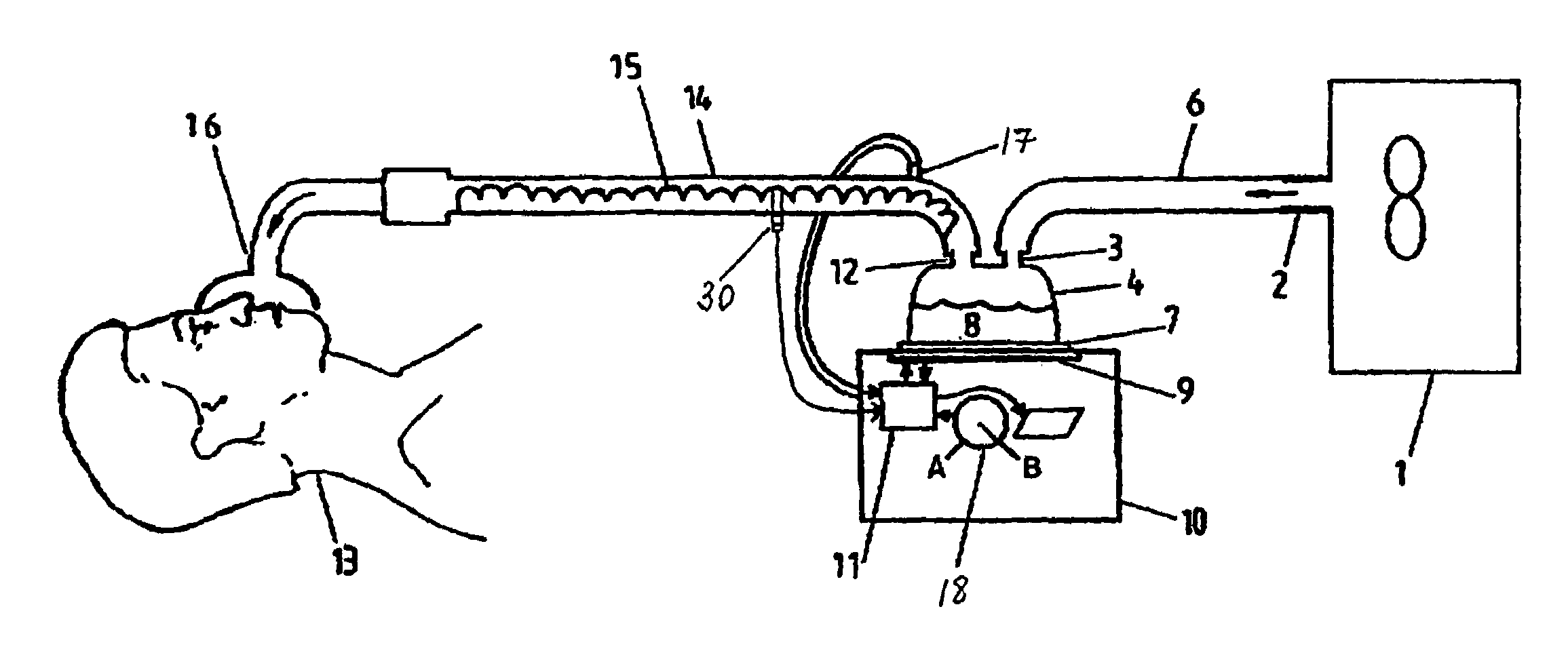
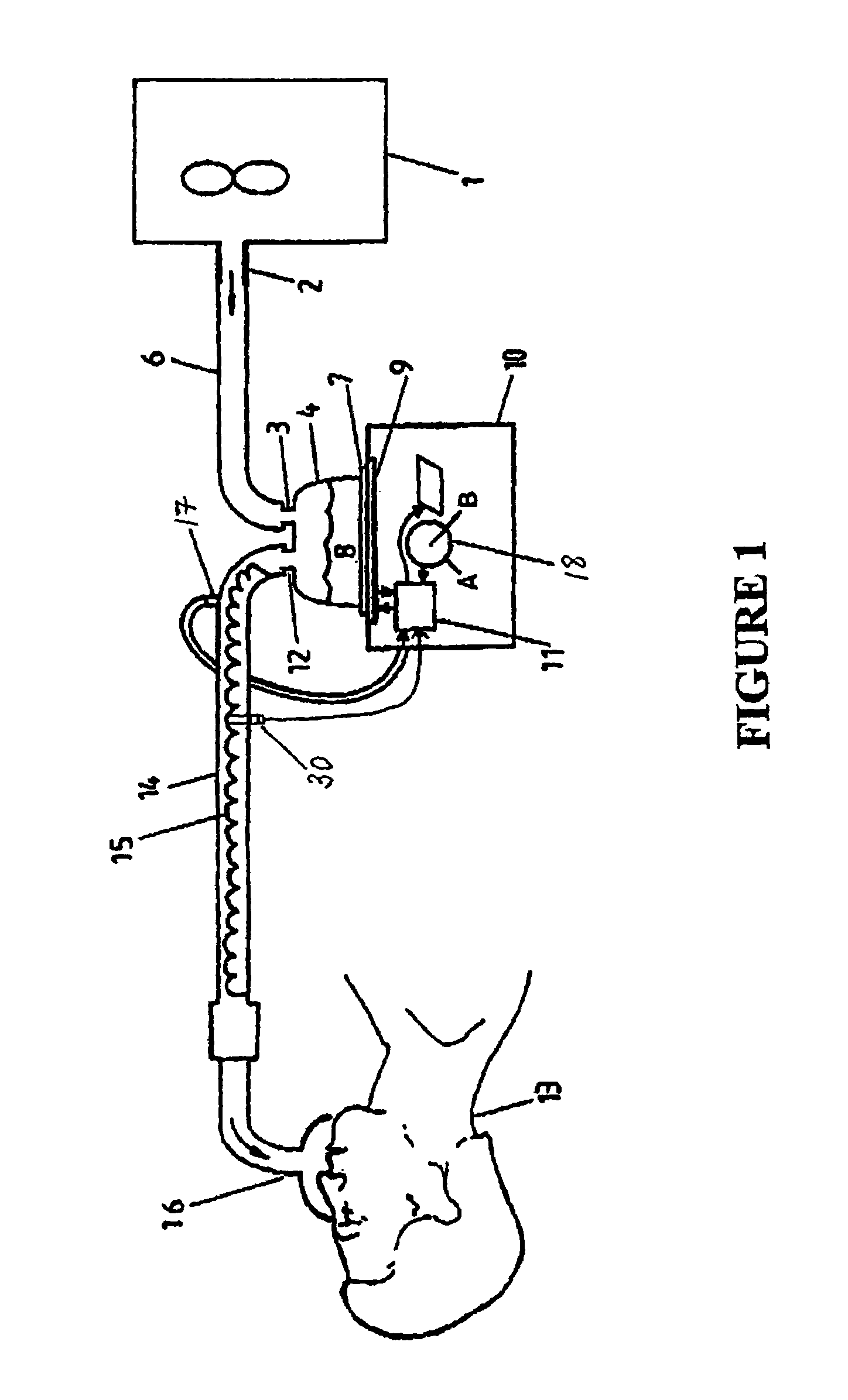
[0038]With reference to the accompanying drawings and in particular to FIG. 1, an example of humidification apparatus or a respiratory humidification system incorporating preferred embodiments of the present invention is illustrated. Included in the respiratory humidification system is a gases supply means 1 (such as a ventilator, insufflator or blower) having an outlet 2, which supplies gases (for example oxygen, anaesthetic gases or air) to the inlet 3 of a humidification chamber means 4 via a conduit 6. Humidification chamber means 4 may, for example comprise a plastics formed chamber having a metal base 7 sealed thereto. Humidification chamber 4 is adapted to hold a volume of water 8, which is heated by a heater plate means 9 under the control of controller or control means 11 of a humidification device or humidifier 10.

[0039]As the water within chamber 4 is heated it will slowly evaporate, mixing water vapour with the gases flow through the humidification chamber from ventilato...


PUM


Abstract

This invention relates to respiratory humidifiers and heated breathing conduits used to couple a patient to the humidifier. A conduit overheating detection system for a conduit having heating wire or element is disclosed. The overheating detection system may be utilized with a in a single limb conduit system or dual limb system. In each of these systems the conduit overheating detection system monitors the current in the heating element(s) and alters the power to the heating element(s) to prevent the occurrence the heating element(s) and / or conduit from overheating.

Description

FIELD OF INVENTION[0001]This invention relates to respiratory humidifiers and heated breathing conduits used to couple a patient to the humidifier. A conduit overheating detection system for the conduit heating wire or element is disclosed.SUMMARY OF THE PRIOR ART[0002]In order to supply gases to a patient or a person needing such gases, it may sometimes be necessary to first humidify those gases, for example using a respiratory humidifier / ventilator system. In such a case where the gases have been humidified, and therefore laden with water, it is likely that during transport through a conduit to the patient, condensation of that water vapour will occur. In order to overcome this disadvantage it is known to associate a heating wire or element with respiratory humidifier breathing conduits to avoid condensation. Examples of such a heated breathing conduit are disclosed in U.S. Pat. No. 5,537,996 (McPhee) and U.S. Pat. No. 5,392,770 (Clawson et al.).[0003]In parts of conduit that cont...

Claims


Application Information

Patent Timeline
Patent Type & Authority Patents(United States)
IPC IPC(8): A61M16/00A61M16/08A61M16/10A61M16/16
CPCA61M16/1075A61M16/16A61M16/1095A61M2016/0039A61M2205/3368A61M16/0841A61M16/024
Inventor WHITE, CRAIG KARLRUMBOLD, DUNCAN JAMES
Owner FISHER & PAYKEL HEALTHCARE LTD
Learn More