
Manually manipulable actuator mechanism having constrained range of motion

a man-made actuator and range of motion technology, applied in the field of man-made actuator mechanisms, can solve problems such as improper operation of the system or the breakage of the actuator mechanism, and achieve the effect of improving the control of the range of motion

Inactive Publication Date: 2006-11-28
VERMILLION DEFENSE
View PDF13 Cites 33 Cited by
  • Summary
  • Abstract
  • Description
  • Claims
  • Application Information

AI Technical Summary

Benefits of technology

The constrained range of motion reduces the risk of system damage, provides a tactile impression of quality and reliability, and ensures proper operation by preventing excessive movement or force application.

Problems solved by technology

The range of motion through which an actuator mechanism moves can influence consumer perception of the overall system because too much “play” in the actuator mechanism is often taken as an indication of poor system design and / or quality.
Moreover, the failure to properly constrain the range of motion of the actuator mechanism can lead to breakage of the actuator mechanism or improper operation of the system, for example, if the actuator mechanism is subject to greater than necessary force or force in a direction other than that required to actuate the system.

Method used


Image

  • Manually manipulable actuator mechanism having constrained range of motion
  • Manually manipulable actuator mechanism having constrained range of motion
  • Manually manipulable actuator mechanism having constrained range of motion

Examples


Embodiment Construction

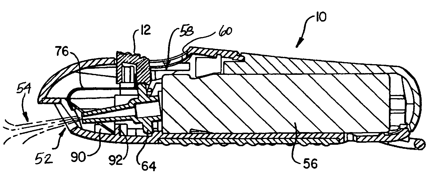
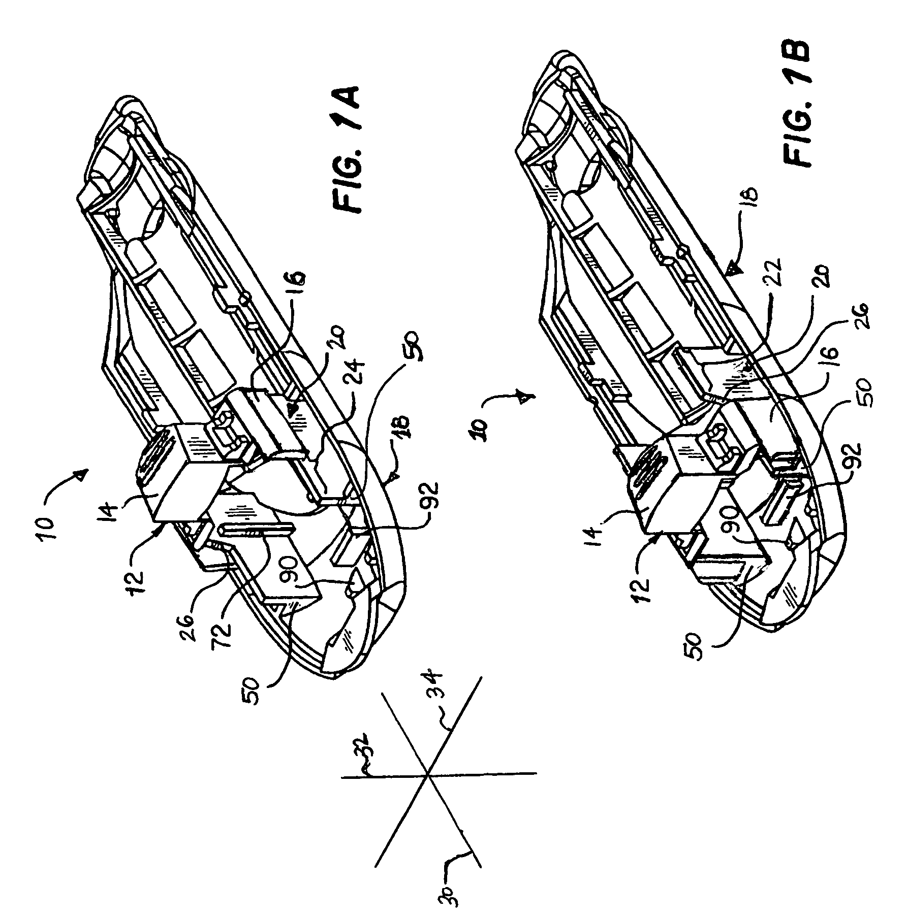
[0018]With reference now to the figures, and in particular with reference to FIGS. 1A–1B, two views of a system 10 having an exemplary actuator mechanism in accordance with the present invention are shown. FIG. 1A depicts system 10 with the actuator mechanism in a first, non-actuated position, and FIG. 1B depicts system 10 with the actuator mechanism in a second, actuated position.

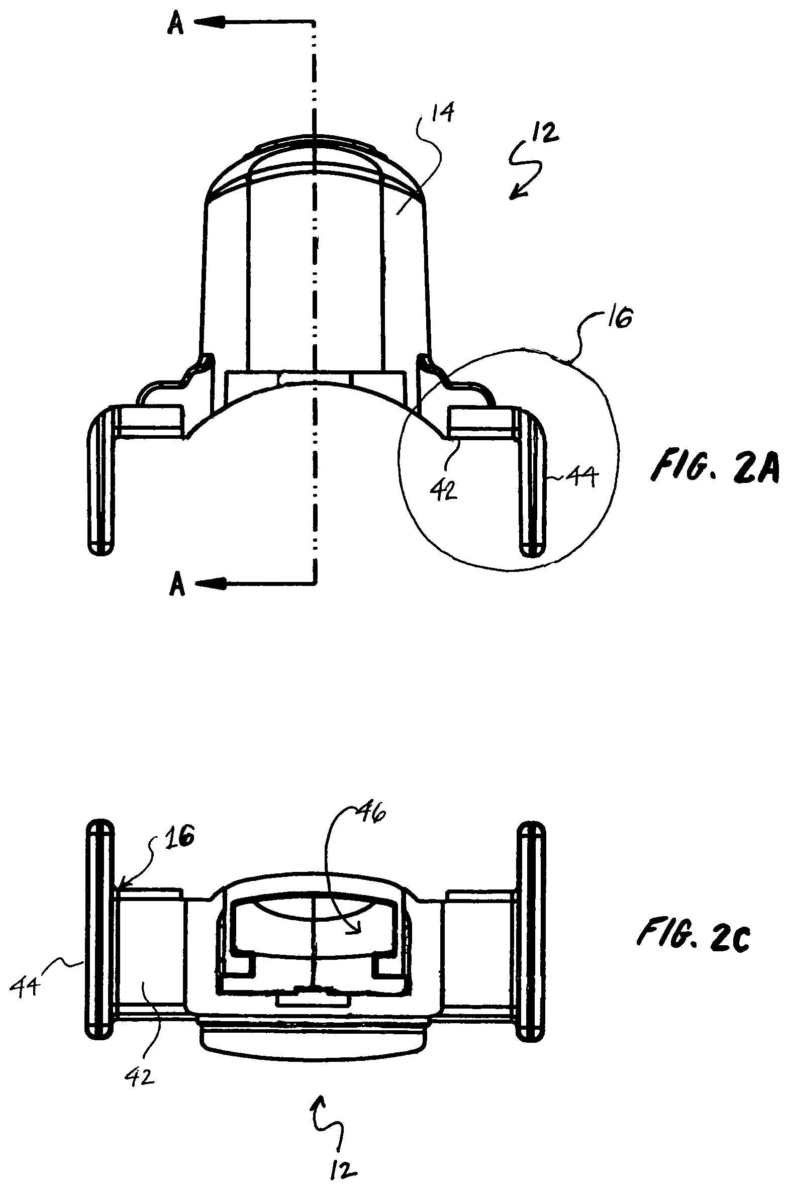
[0019]The actuator mechanism includes at least a manually manipulable element 12 and a means for constraining the range of motion of manually manipulable element 12. In the depicted embodiment, the means for constraining the range of motion of manually manipulable element 12 includes at least one and in this case, two wall portions 20 of a body 18 within system 10. Wall portions 20, which are generally parallel, have a length generally extending along a first axis 30 and a height generally extending along an orthogonal second axis 32. Wall portions 20 may be integrally formed with body 18 (e.g., by molding...


PUM


Abstract

A manually manipulable actuator mechanism includes a body and a manually manipulable element. The body has at least one wall element having a length extending along a first axis and a height extending along a second axis orthogonal to the first axis. The manually manipulable element has a button portion adapted for human digital manipulation and at least one wing portion extending outwardly from the button portion. The manually manipulable element is movable along the first axis between a first position in which an operative element is in a non-actuated condition and a second position in which the operative element is in an actuated condition. The wall element, which has a first height at the first position and a different second height at the second position, cooperates with the wing portion to constrain movement of the manually manipulable element at least along a third axis orthogonal to the first and second axes while the manually manipulable element is moved between the first and second positions.

Description

CROSS-REFERENCE TO RELATED PATENT[0001]The present application is related to U.S. Pat. No. 6,199,726, which is incorporated herein by reference in its entirety as background material.BACKGROUND OF THE INVENTION[0002]1. Technical Field[0003]The present invention relates in general to actuator mechanisms, and in particular, to manually manipulable actuator mechanisms having a constrained range of motion.[0004]2. Description of the Related Art[0005]Manually manipulable actuator mechanisms are commonly employed to actuate or facilitate the operation or function of electronic, electromechanical and mechanical systems. These manually manipulable actuator mechanisms include a wide variety of push buttons, switches, dials, sliders, knobs, triggers and other actuator mechanisms.[0006]A primary consideration in the design of an actuator mechanism is the range of motion through which the actuator mechanism will be permitted to move when subjected to anticipated levels of manual force. The rang...

Claims


Application Information

Patent Timeline
Patent Type & Authority Patents(United States)
IPC IPC(8): B67D5/06B67D7/06F41H9/10
CPCF41H9/10
Inventor CARDWELL, III, WALTER WILCOXANDERSON, JON
Owner VERMILLION DEFENSE
Learn More