
Surgical stapling instrument having an electroactive polymer actuated single lockout mechanism for prevention of firing

a single lockout mechanism and surgical staple technology, applied in the direction of surgical staples, surgical staples, surgical forceps, etc., can solve the problem of economic inefficiency of replacing an entire end effector for each operation

Inactive Publication Date: 2006-11-28
CILAG GMBH INT
View PDF31 Cites 2190 Cited by
  • Summary
  • Abstract
  • Description
  • Claims
  • Application Information

AI Technical Summary

Benefits of technology

[0011]The invention overcomes the above-noted and other deficiencies of the prior art by providing a single lockout mechanism that prevents firing a surgical stapling and severing instrument when either a staple cartridge is not installed or is spent. In particular, the single lock mechanism prevents distal movement of a firing bar, and thus severing of tissue, in instances where simultaneous stapling would not occur.
[0013]In another aspect of the invention, a surgical instrument that includes upper and lower jaws for clamping, severing and stapling tissue by receiving a firing bar advantageously includes a lockout device positioned within the implement portion to block this firing motion when conditions requisite to firing are not present. Thereby, inadvertent severing is prevented when effective stapling is not assured.

Problems solved by technology

Replacing an entire end effector for each operation tends to be economically inefficient.

Method used


Image

  • Surgical stapling instrument having an electroactive polymer actuated single lockout mechanism for prevention of firing
  • Surgical stapling instrument having an electroactive polymer actuated single lockout mechanism for prevention of firing
  • Surgical stapling instrument having an electroactive polymer actuated single lockout mechanism for prevention of firing

Examples


Embodiment Construction

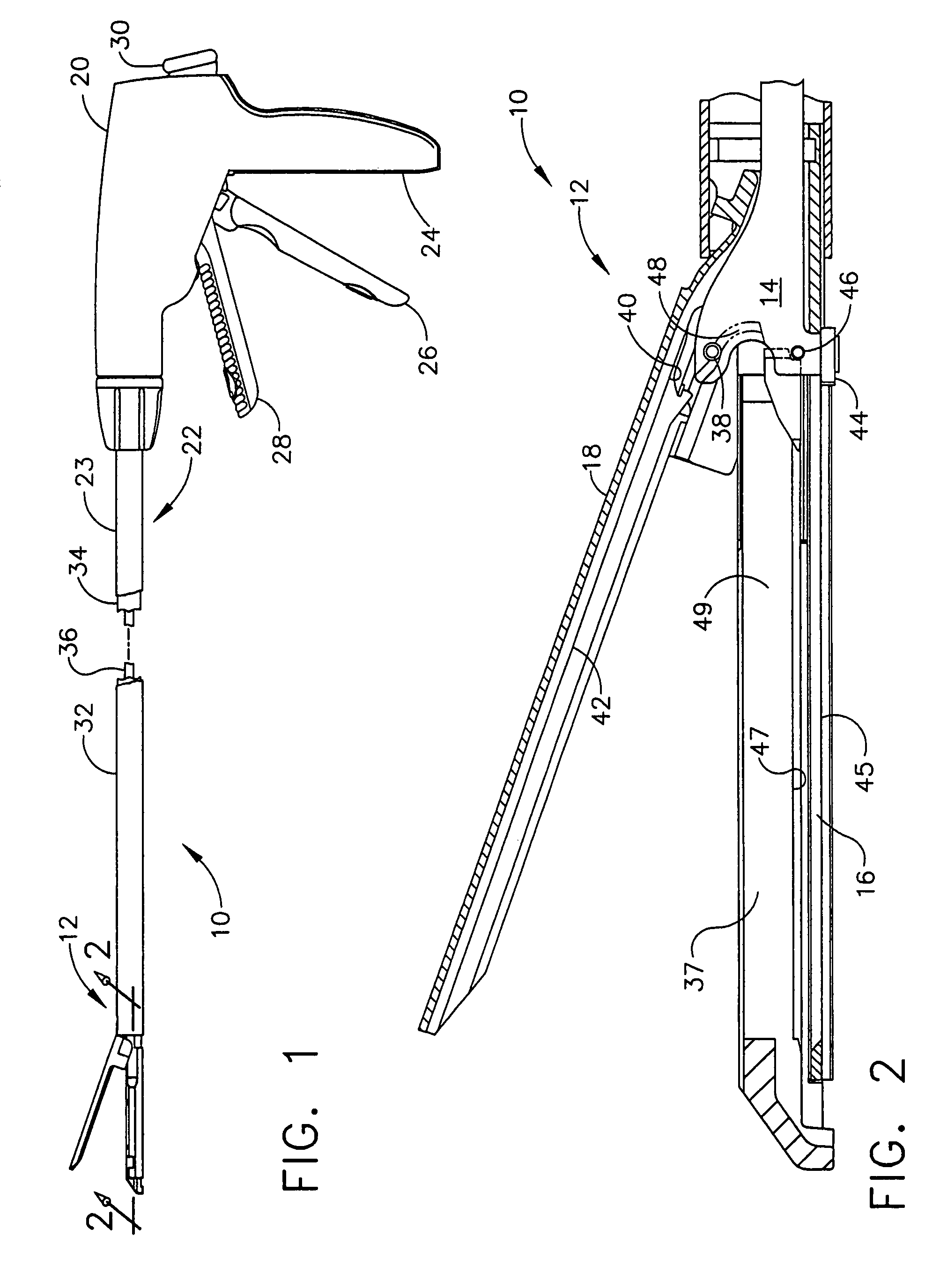
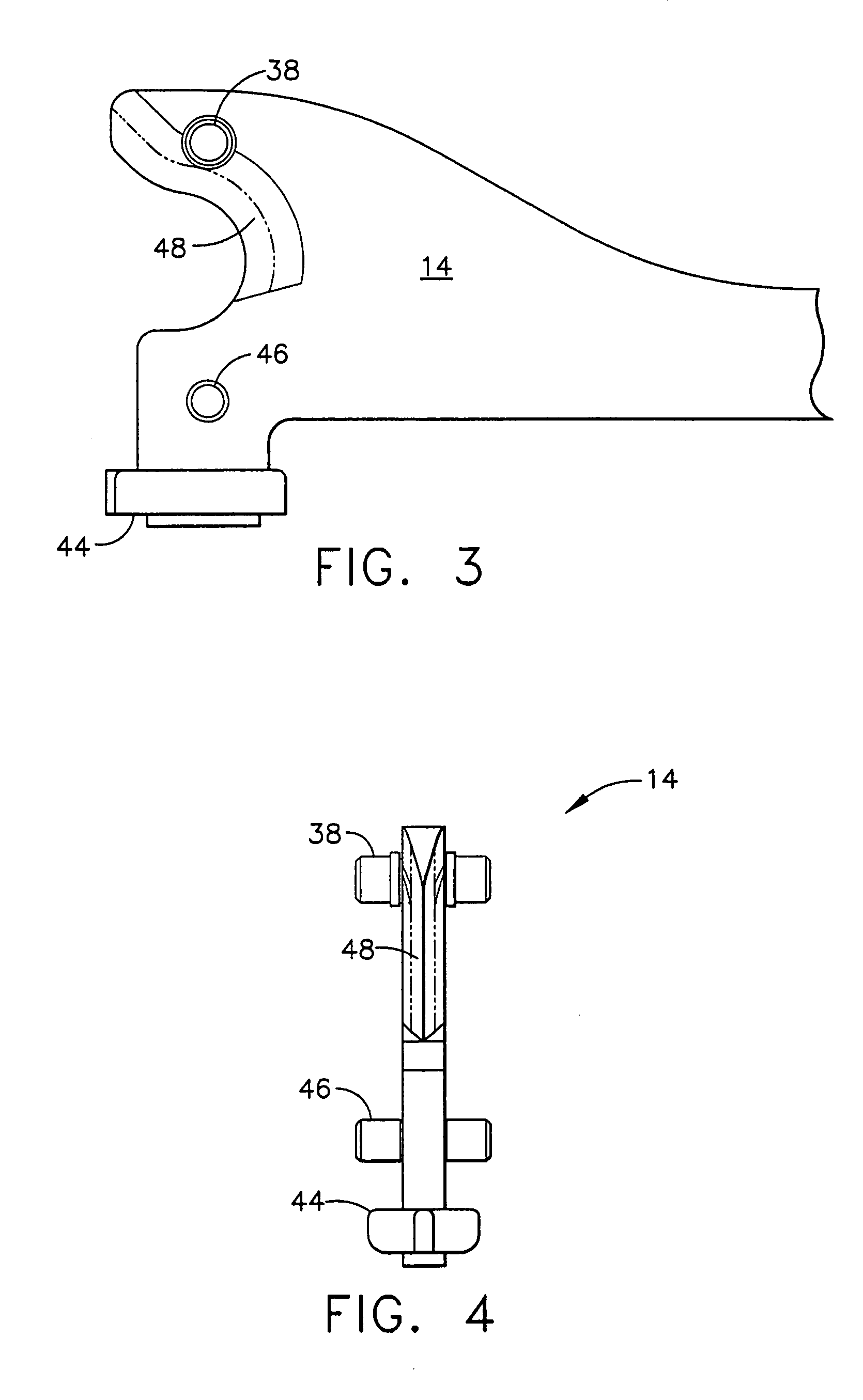
[0052]Turning to the Drawings, wherein like numerals denote like components throughout the several views, FIGS. 1 and 2 depict a surgical stapling and severing instrument 10 that is capable of practicing the unique benefits of the present invention. The surgical stapling and severing instrument 10 incorporates an end effector 12 having an E-beam firing mechanism (“firing bar”) 14 that advantageously controls the spacing of the end effector 12. In particular, an staple channel 16 and a pivotally translatable anvil 18 are maintained at a spacing that assures effective stapling and severing. Furthermore, firing (i.e., severing and stapling ) is prevented from occurring if the instrument is not capable of stapling with a single lockout mechanism, which is described in more detail below.

[0053]The surgical and stapling and severing instrument 10 includes a handle portion 20 connected to an implement portion 22, the latter further comprising a shaft 23 distally terminating in the end effec...


PUM

PropertyMeasurementUnit
angleaaaaaaaaaa
voltage potentialaaaaaaaaaa
electrical signalaaaaaaaaaa

Abstract

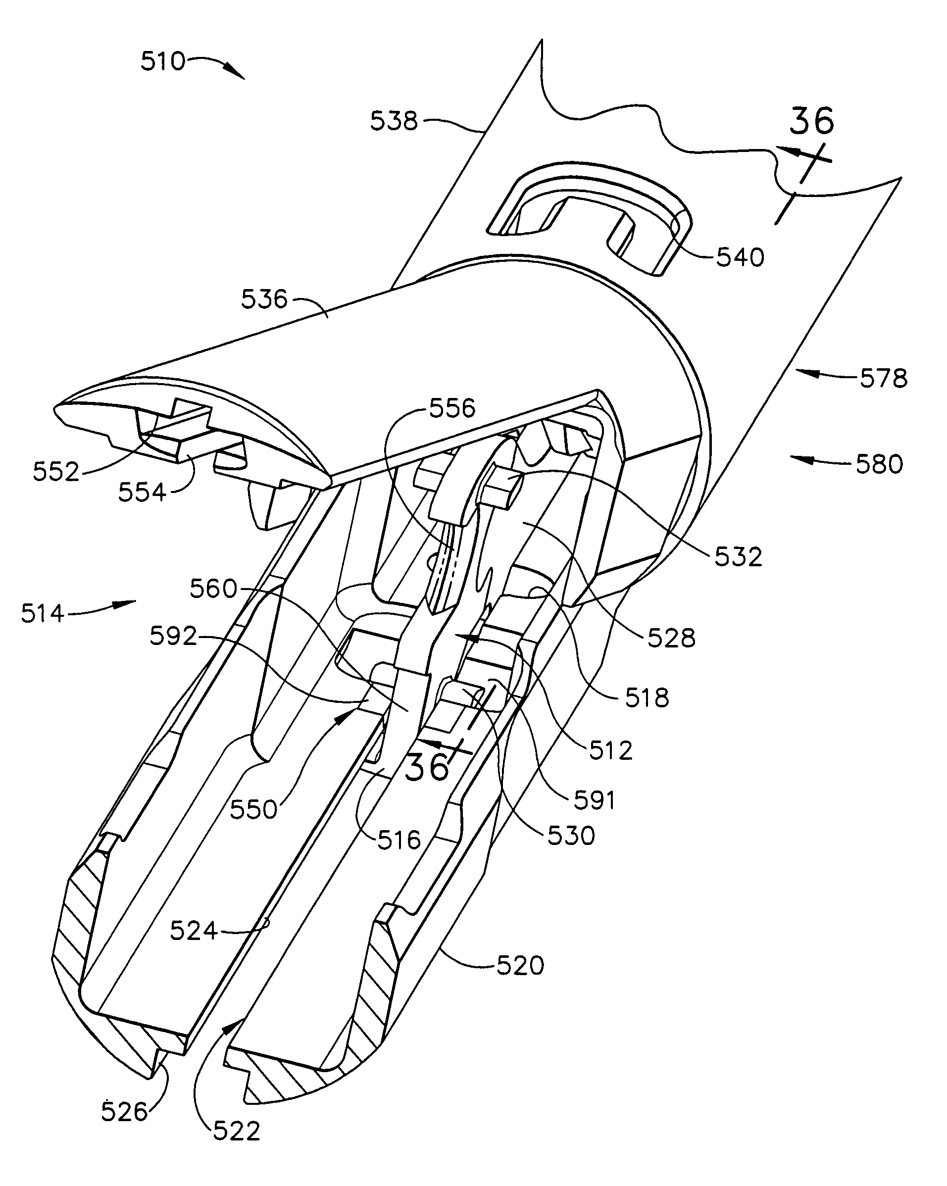
A surgical instrument includes an E-beam firing bar engages the channel and selectively engages the anvil during distal firing movements, wherein the tissue is severed and stapled driven upward from the staple cartridge to form against the anvil. In particular, a wedge integral to the staple cartridge is driven distally by a middle pin of the firing bar to effect stapling. A single lockout of the staple channel responds to the presence of the wedge sled in its unfired position to allow the firing bar to fire. Otherwise, the single lockout prevents firing when the staple cartridge is missing or spent. Further, some versions include an Electroactive Polymer (EAP) actuator that presents an abutting surface, or acts as a trapdoor to a ramped recess in a staple channel to block the firing bar, as an active approach to preventing firing for one or more conditions.

Description

CROSS REFERENCE TO RELATED APPLICATIONS[0001]The present application is a continuation in part of U.S. patent application Ser. No. 10 / 441,424, U.S. patent application Ser. No. 7,044,352 filed 20 May 2003, entitled “SURGICAL STAPLING INSTRUMENT HAVING A SINGLE LOCKOUT MECHANISM FOR PREVENTION OF FIRING” to Frederick E. Shelton IV, Michael Earl Setser, and William Bruce Weisenburgh II, the disclosure of which is hereby incorporated by reference in its entirety.[0002]This application claims the benefit of U.S. provisional application Ser. No. 60 / 591,694, entitled “SURGICAL INSTRUMENT INCORPORATING AN ELECTRICALLY ACTUATED ARTICULATION MECHANISM” to Shelton IV, filed 28 Jul. 2004.FIELD OF THE INVENTION[0003]The present invention relates in general to surgical stapler instruments that are capable of applying lines of staples to tissue while cutting the tissue between those staple lines and, more particularly, to improvements relating to stapler instruments and improvements in processes f...

Claims


Application Information

Patent Timeline
Patent Type & Authority Patents(United States)
IPC IPC(8): A61B17/068A61B17/072
CPCA61B17/07207A61B2017/00367A61B2017/00398A61B2017/00871A61B2017/07214A61B2017/07285A61B2019/481A61B2019/4873A61B2090/08021A61B2090/0814A61B2017/00017A61B2017/00867A61B2017/2927A61B17/115A61B17/00A61B17/068
Inventor SHELTON, IV, FREDERICK E.
Owner CILAG GMBH INT
Learn More