Seat, particularly a vehicle seat, preferably in an aeroplane

a vehicle seat and seat technology, applied in the field of seats, can solve the problems of frame structure, adversely affecting the safety of known seat designs, adversely affecting sitting comfort, etc., and achieve the effect of ensuring a high level of safety

Inactive Publication Date: 2006-11-28
RECARO AIRCRAFT SEATING GMBH & CO KG
View PDF7 Cites 15 Cited by
  • Summary
  • Abstract
  • Description
  • Claims
  • Application Information

AI Technical Summary

Benefits of technology

[0005]An object of the present invention is to provide improved seats, especially vehicle seats, such as aircraft passenger seats, where the seat, as a complete system, ensures a high level of safety even in case of a crash, and still provides a plurality of adjustment possibilities for the seat, especially relative to the height and tilt adjustment of the actual seat part.
[0006]Another object of the present invention is to provide an improved seat movement mechanism which will require only little installation space on the seat and will be economical to implement.
[0007]These objects are achieved by a seat with a movement mechanism producing the movable coupling between the respective control part and the assignable stiffening part by at least one coupling part. In the initial position, the respective stiffening part is located essentially parallel to the lengthwise orientation of the actuating means. The forces which occur in a crash are diverted by the actuating means with the respective stiffening part into the floor structure, for example, in the form of a vehicle or aircraft cabin floor in a reliable and dedicated manner. The actuating means keeps the stationary legs apart at least in the initial position in the case of a crash such that the seat frame structure of the overall seat is preserved in any case. Accordingly, the individual seat components are essentially preserved in their structure. In case of a crash, damage is diverted away from the respective seat occupant. Since in case of a crash one of the main loading directions, as a result of the weight of the seat occupant, occurs on the rear seat edge of the seat part, the loading forces which occur there are diverted at an angle of approximately 45° in the raised seat position into the respective vehicle or aircraft cabin floor.
[0008]By using another coupling part, the movement and adjustment possibilities for the actuating means in conjunction with the stationary legs and for the respective stiffening part can be enhanced. The seat with its seat part can then be adjusted almost at will, not only in height in the given frame, but at least relative to the seat part. A plurality of tilt adjustments is easily possible by the slaved stationary legs. This adjustment could not be achieved in the past in this form with the known designs (cf. U.S. Pat. No. 2,784,764).
[0009]In one preferred embodiment of the seat of the present invention, the actuating means has an actuator connected on the housing side to the base frame by which the seat can be joined to the floor structure. On the rod side, the actuator has a multipart movement mechanism which interacts with a moving axle extending between the two stationary legs pivotally coupled to the seat frame structure in the area of the transition between the seat part and the backrest. Without limiting possible movements in this way, especially the tilt adjustment possibilities for the seat, a stiff seat frame is clamped and can accommodate the loads which occur in a crash equally in all directions. The moving axle as a tubular stiffening segment, by preference, keeps the two rear stationary legs at a distance. Other tubular stiffening segments extend between the moving axle and the movement mechanism.

Problems solved by technology

This jerking can adversely affect sitting comfort.
In case of a crash, this arrangement can lead to the seat frame structure, including the stationary legs, collapsing and accordingly adversely affects the safety of known seat designs.

Method used


Image

  • Seat, particularly a vehicle seat, preferably in an aeroplane
  • Seat, particularly a vehicle seat, preferably in an aeroplane
  • Seat, particularly a vehicle seat, preferably in an aeroplane

Examples


Embodiment Construction

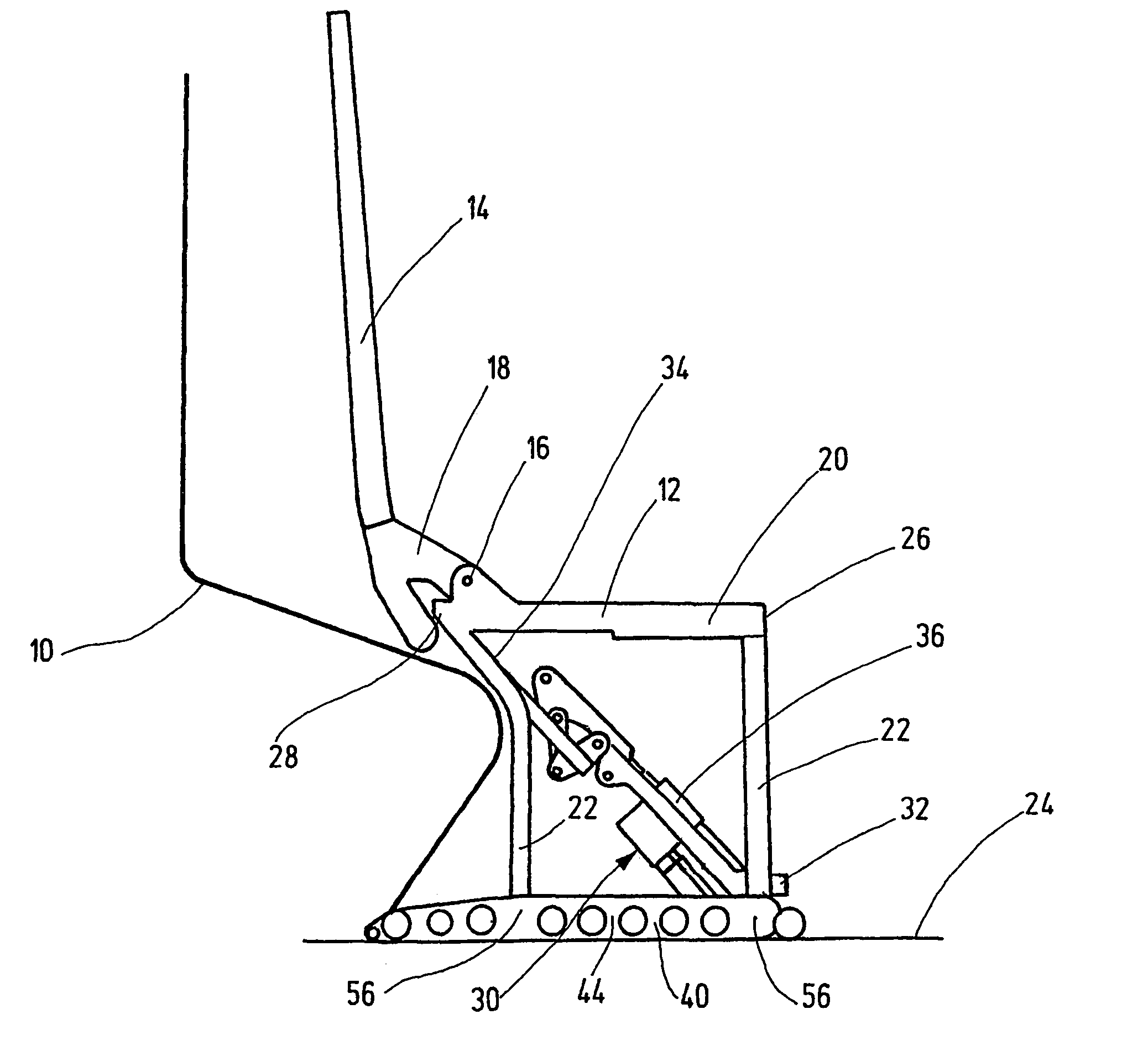
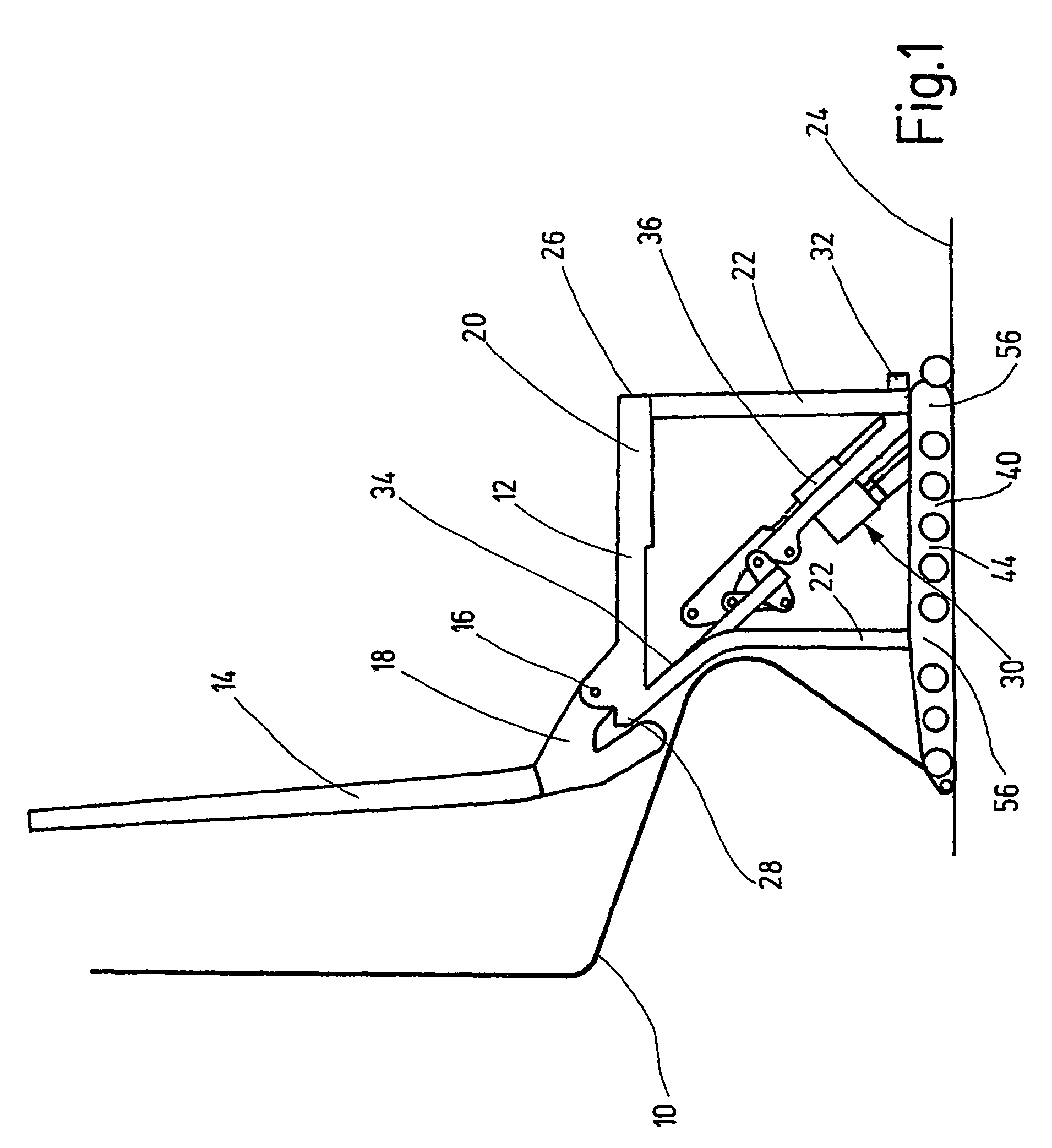
[0019]FIG. 1 shows an aircraft passenger seat in the upright position. Such aircraft passenger seats with the corresponding level of outfitting are often found in the first class compartment of long-range aircraft. They could also be used in luxury tour busses or in passenger ships including ferries. Furthermore, the seat can be used as a medical treatment chair for surgery or dentistry. Other applications are in sports medicine and as a chair for the application of cosmetics.

[0020]The illustrated aircraft passenger seat, as shown in FIG. 1, is preferably a component of a compartment which is shown by suggestion in FIG. 1. The aircraft passenger seats could also be used in arrangements next to one another in a row in business class for a conventional multiseat arrangement or the like.

[0021]The aircraft passenger seat comprises individual seat components, such as a seat part 12, a backrest 14 and a leg rest system which is not detailed. For greater clarity, the cushion supports for t...


PUM


Abstract

A seat includes at least one inclinably adjustable seat component, such as a seat section (12), whose seat frame structure can be disposed on a floor structure (24) in such a way that the seating section is pivotable around its stationary legs (22). The pairs of stationary legs (22) in the region of the front edge (26) and the rear edge (28) of the seating section (12) act upon the seating section. An actuating device (30) adjusts the respective inclination of the seat section (12), and has an exit position, whereby the seat section (12) is orientated in an essentially parallel manner in relation to the floor structure (24) and cannot be inclined. The actuating device (30) extends in the exit position between the stationary legs (22), whereby one end (32) in the region of the front seat (26) is orientated counter to the floor structure (24) and the other end (34) in the region of the rear edge of the seat (28) is orientated in the direction of the seat frame structure (20). As a result, forces arising from a crash are deflected by the actuating device in a safe and targeted manner to the floor structure. The actuating device strives to maintain its original position in the seat frame structure when a crash occurs.

Description

FIELD OF THE INVENTION[0001]The present invention relates to a seat, particularly a vehicle seat, preferably for an aeroplane. At least one seat component is adjustable at least in its height, like a seat part, and can be erected with its seat frame structure to be able to swivel on stationary legs on a floor structure. The stationary legs are in pairs in the area of the front seat edge and back seat edge of the seat part, and are engaged in the latter. An actuation means has a multipart movement mechanism with at least one control part for adjusting the respective height for the seat part. In an initial position, the seat part is aligned essentially parallel to the floor structure, with the actuation means extending between the stationary legs such that one actuation means end in the area of the front seat edge points against the floor structure and the other actuation means end in the area of the back seat edge points in the direction of the seat frame structure. At least one stif...

Claims


Application Information

Patent Timeline
Patent Type & Authority Patents(United States)
IPC IPC(8): A47C1/02B60N2/00B60N2/18B60N2/42B60N2/427B60N2/50B64D11/06B64D25/04
CPCB60N2/1615B60N2/1635B60N2/1695B60N2/1814B64D11/06395B64D25/04B64D11/064B64D11/06Y02T50/46B64D11/0696B64D11/0648Y02T50/40
Inventor WAGNER, WOLFGANGBAUMANN, JURGEN
Owner RECARO AIRCRAFT SEATING GMBH & CO KG
Why Eureka
Try Eureka