
Mechanical lock mechanism for locking wiper/printhead

a mechanical lock and wiper technology, applied in printing and other directions, can solve the problems of unrestrained wiper mechanism, unrestrained unrestrained and unrestrained wiper mechanism, etc., to reduce or prevent damage to printhead and/or drum using minimal parts. , the effect of reducing or avoiding the unrestrained wiper mechanism

Inactive Publication Date: 2006-11-28
XEROX CORP
View PDF4 Cites 6 Cited by
  • Summary
  • Abstract
  • Description
  • Claims
  • Application Information

AI Technical Summary

Benefits of technology

The patent describes a locking mechanism for a device that moves a wiper to clean the surface of a printhead. The mechanism includes a support member, a pivot, and a rotating member that locks the device when it reaches its maximum travel. The mechanism is designed to prevent unintended movement of the wiper, which could cause damage to the printhead and drum. The locking mechanism is simple and cost-effective, and can be easily unlocked and secured. The technical effects of this invention are to reduce the risk of damage to the printhead and drum, and to provide a reliable and secure locking mechanism for the wiper mechanism.

Problems solved by technology

Without the engagement of the wiper mechanism to the drive motor through the clutch, the wiper mechanism is unrestrained and unintended movement of the wiper may occur.
Unrestrained and unintended movement of the wiper may occur, for example, when the device is transported from one location to another location whereby such movement of the device may cause the wiper and its mechanism to disengage.
In such devices, the wiper, which is unrestrained, may unintentionally move from the upper position to the lower position away from the space defined by the printhead and the drum.
Further, if the vibration from the relocation or the movement of the device is great, the printhead can slam into the drum without being caught by an intervening wiper.
Such unintended contact may damage the drum and / or the printhead.

Method used


Image

  • Mechanical lock mechanism for locking wiper/printhead
  • Mechanical lock mechanism for locking wiper/printhead
  • Mechanical lock mechanism for locking wiper/printhead

Examples


Embodiment Construction

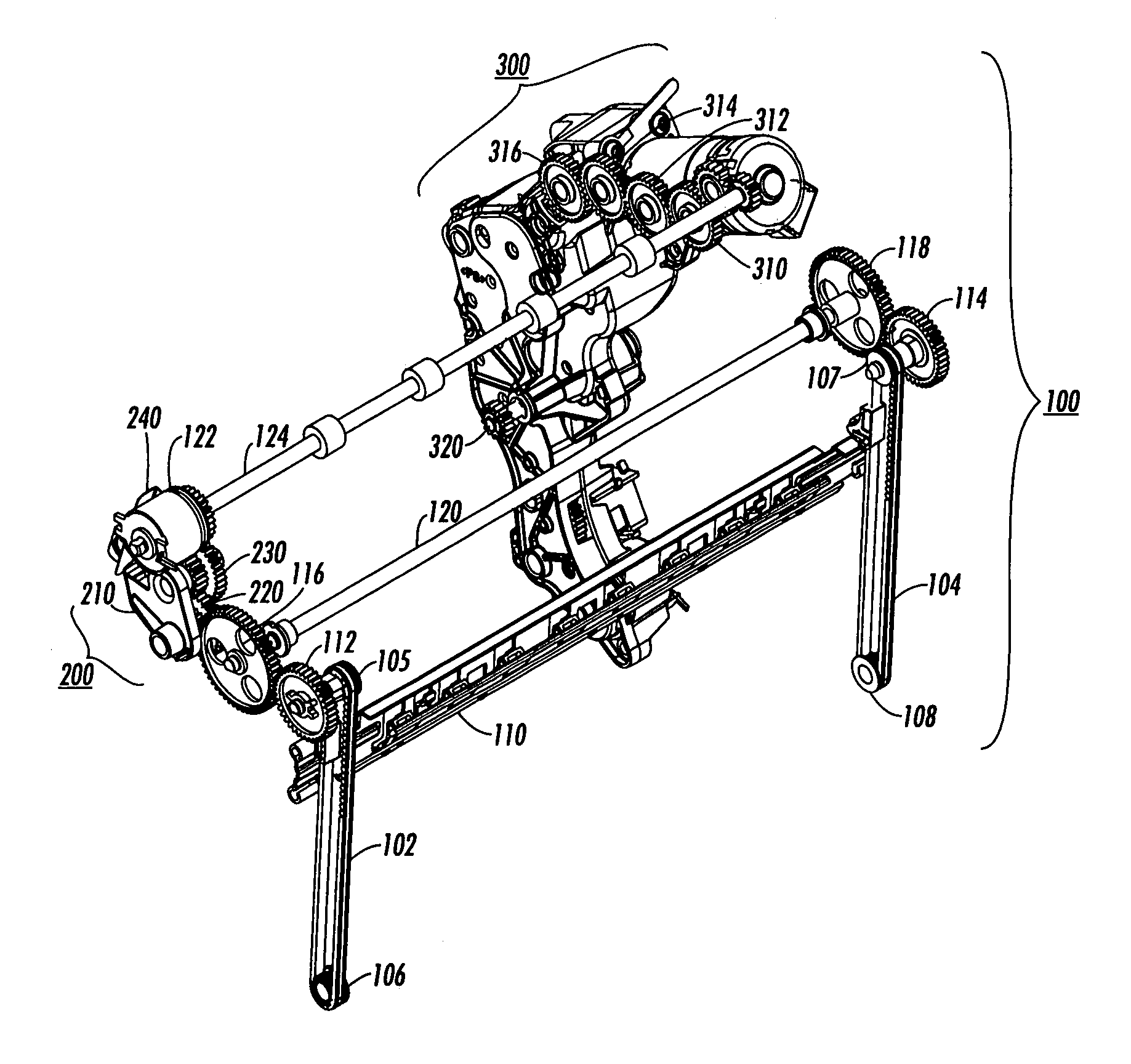
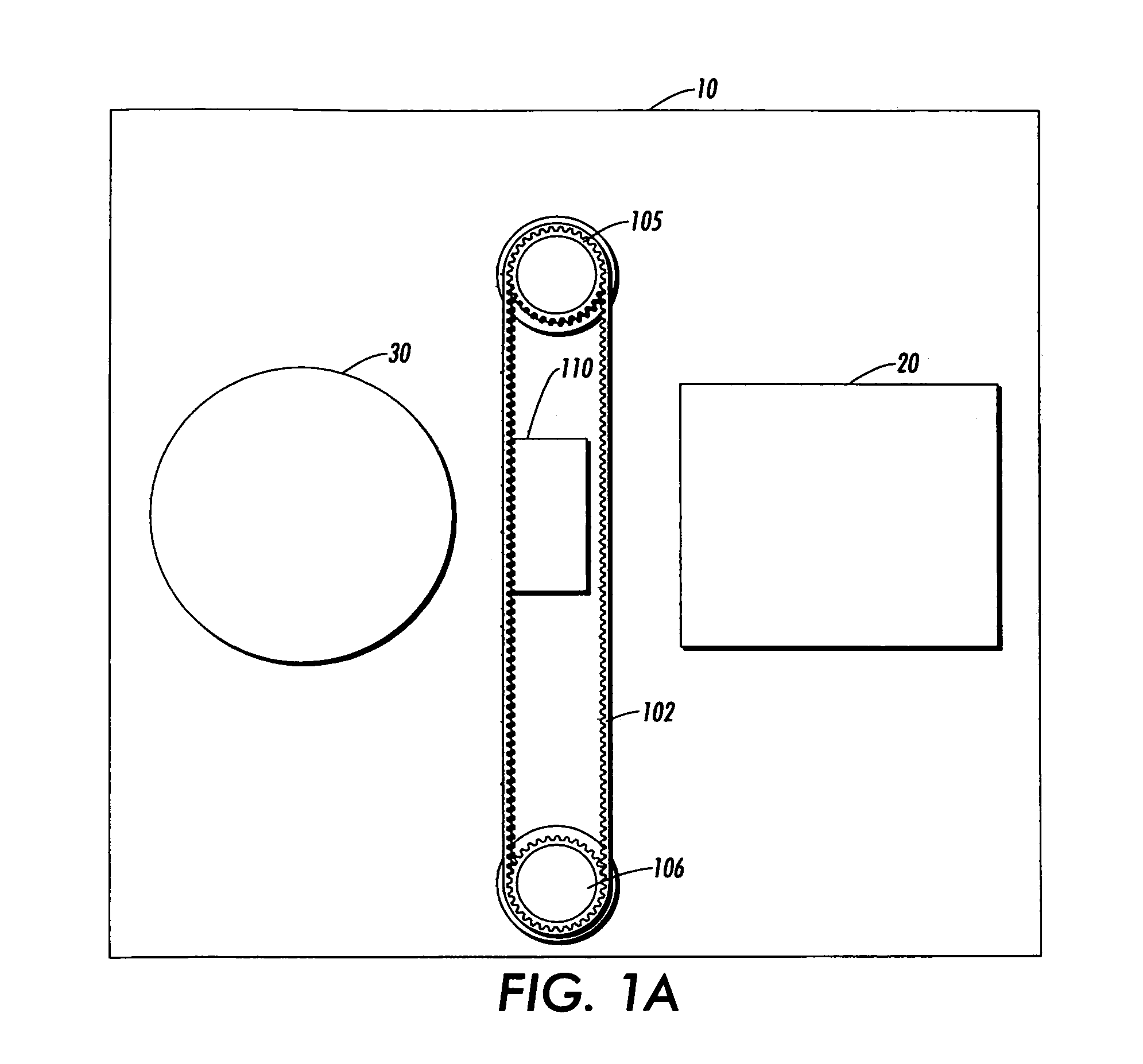
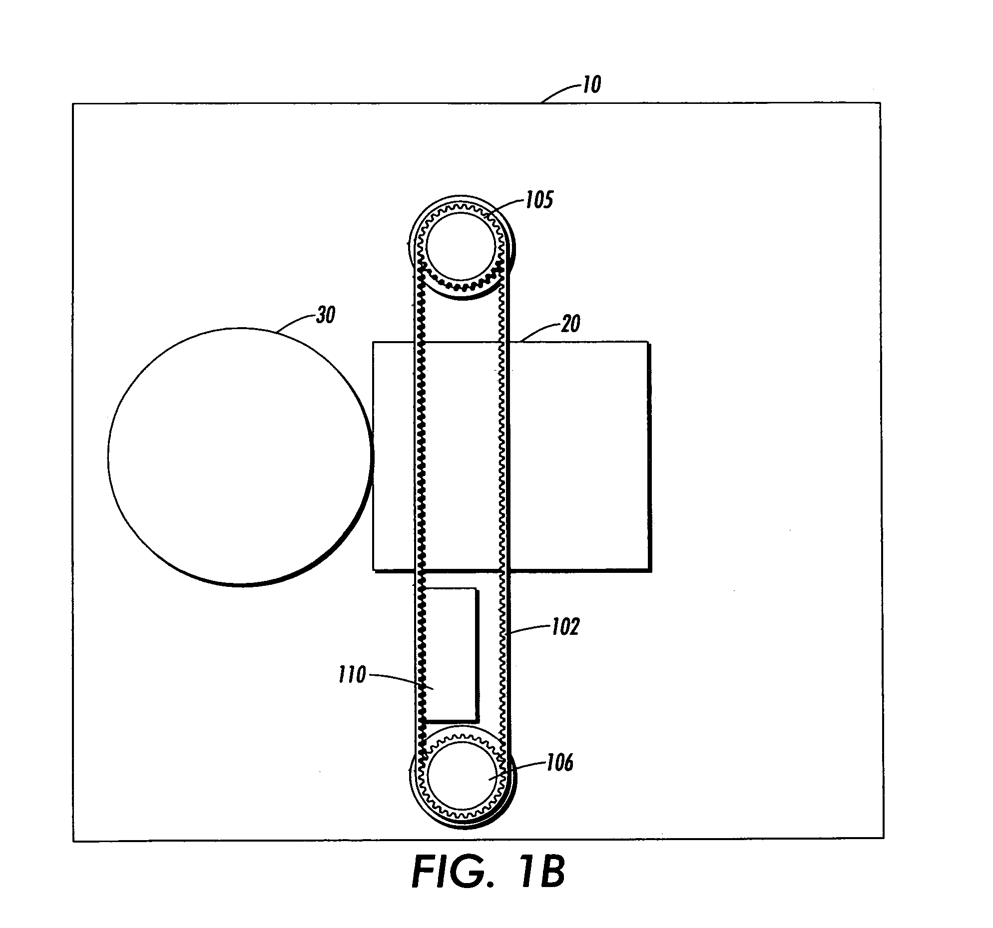
[0031]For a general understanding of a wiper / printhead mechanism of a copier / printer in which the features of this invention may be incorporated, reference is made to FIGS. 1A–1D, which depict various key components thereof. Although this invention for locking the wiper / printhead is particularly well adapted for use in such a machine, it should be apparent that the embodiments are merely illustrative. Rather, aspects of this invention may be achieved in any wiper / printhead copier / printer system in which a wiper used is subject to unexpected and unintended movement and / or contact of the wiper with the drum or printhead.

[0032]In FIGS. 1A–1D, a copier / printer 10 contains various components which allow production and / or reproduction of printed text and / or images on a medium such as paper. Some of these components are a printhead 20, which is used to eject ink directly onto a drum 30 as shown in FIGS. 1A–1D. Disposed between the printhead 20 and the drum 30 is a positioning system 40 whi...


PUM


Abstract

A locking mechanism in an image processing device is needed to lock a movable element of the image processing device. In embodiments, the locking mechanism has a support member disposed between the driving element and the movable element, the support member being movable between a first position and a second position, a pivot on the support member about which the support member is able to rotate, and a first rotating member on the support member, the first rotating member rotating when the movable element is moved by the driving element, and the locking mechanism is locked when both the first rotating member is stopped from rotating and the support member is rotated from the first position to the second position about the pivot.

Description

BACKGROUND OF THE INVENTION[0001]1. Field of Invention[0002]The invention relates to systems and methods for locking a wiper / printhead using a lock mechanism.[0003]2. Description of Related Art[0004]Certain types of devices, such as printers or copiers, create an image on a medium, such as paper, by ejecting ink through orifices formed in an orifice plate attached to a printhead onto the medium, or a drum that transfers an image formed on the drum to the medium. In devices that use the drums, a latent image is first formed on the rotating drum and ink is then ejected from the printhead onto the drum. The image, which is eventually transferred to the medium, is in the shape of the latent image formed on the rotating drum.[0005]In devices that eject ink from the printhead, repeated use of the device allows contaminants to form. These contaminants may consist of ink or other debris in the orifices and the orifice plate of the printhead. Accordingly, the printheads must be periodically ...

Claims


Application Information

Patent Timeline
Patent Type & Authority Patents(United States)
IPC IPC(8): B41J2/165B41J23/00
CPCB41J2/16535
Inventor JENSEN, DARRYL I.HANEY, MARCIA D.ESPLIN, ERNEST I.
Owner XEROX CORP
Learn More