
Method and apparatus for a reference clock buffer system

a clock buffer and reference clock technology, applied in the field of clock buffers, can solve the problems of significant interference with system performance and reliability, noise from power supply, and not always constant, and achieve the effect of reducing power supply and noise-induced jitter

Active Publication Date: 2006-11-28
XILINX INC
View PDF10 Cites 52 Cited by
  • Summary
  • Abstract
  • Description
  • Claims
  • Application Information

AI Technical Summary

Benefits of technology

The patent describes a system that reduces power-supply and noise-induced jitter on an output signal of a buffer. This is achieved by using a buffer that operates independently of its environment by deriving temperature-independent bias signals from two power supplies with different levels. The buffer includes a current generator that generates a current bias that is independent of temperature variations. This results in a more stable output signal from the buffer, regardless of changes in temperature.

Problems solved by technology

The technical problem addressed in this patent text is the need for a buffer circuit that can effectively reduce power supply induced jitter, while also being adaptable to different applications and system parameters. This is important for improving the performance and reliability of communication circuits that require high data rates and reliable clock signals.

Method used


Image

  • Method and apparatus for a reference clock buffer system
  • Method and apparatus for a reference clock buffer system
  • Method and apparatus for a reference clock buffer system

Examples


Embodiment Construction

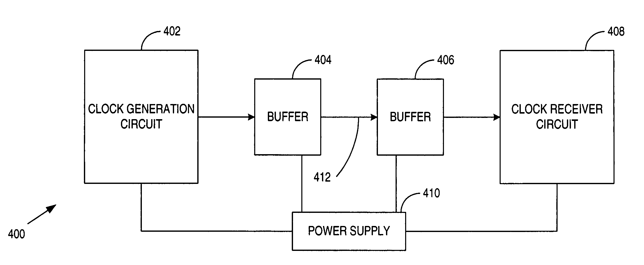
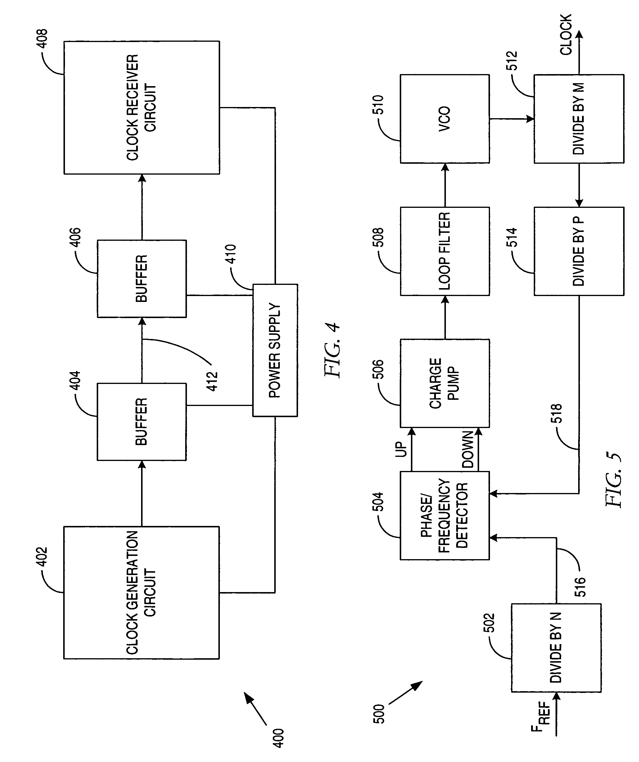
[0028]Various embodiments of the present invention are described in terms of buffer circuits that minimize the jitter contribution of the power supply. Embodiments of buffer circuits used to propagate a signal are shown using complimentary P-type Field Effect Transistors (PFET) and N-type (NFET) topologies. Those skilled in the art will appreciate that the invention could be implemented in other circuit topologies such as bipolar or bipolar-Complimentary Metal Oxide (biCMOS) circuit topologies.

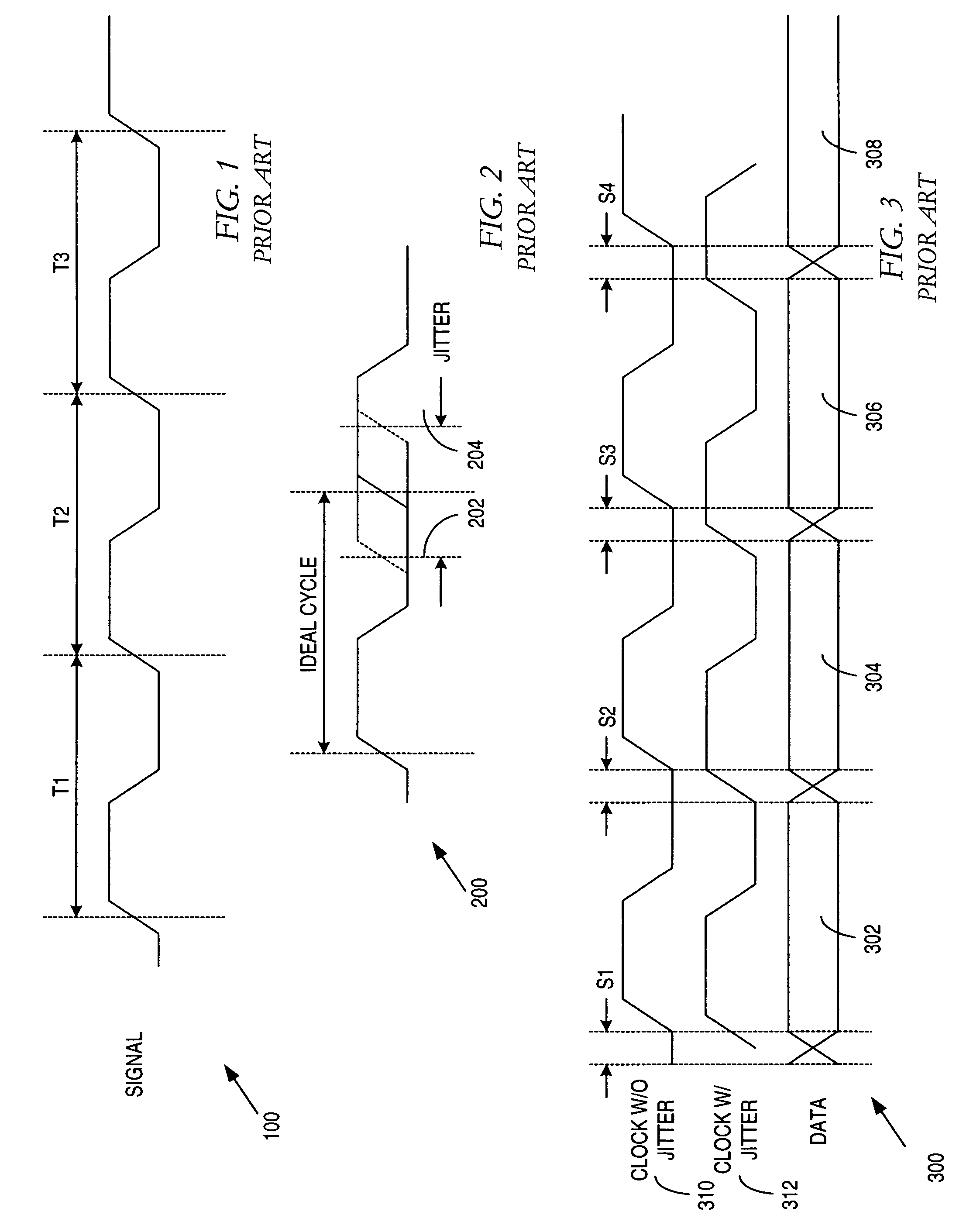
[0029]Jitter may be defined as the deviation in a signal's actual transition in time from its ideal position in time, the signal's actual transition may either lag or lead the ideal position in time. Jitter may be classified into three categories: cycle to cycle jitter, period jitter, and long term jitter.

[0030]Cycle to cycle jitter is the change in a signal's output transition from its corresponding position in the previous cycle as shown in FIG. 1. The total amount of cycle to cycle jitter, ...


PUM


Abstract

According to one example embodiment, a buffer, e.g., in a clock/signal distribution apparatus is provided that substantially reduces jitter due to power supply noise. Decoupler and input stage isolates load from the top rail power supply (VDD). In a more particular embodiment, jitter contributions from the bottom rail power supply (VSS) can be minimized by cross-coupled load devices within load. Substantial independence from process and temperature is facilitated through the use of current bias, such as Proportional to Absolute Temperature (PTAT) current bias.

Description


Claims


Application Information

Patent Timeline
Owner XILINX INC
Learn More