Flexible engine and data structure for packet header processing

a data structure and packet header technology, applied in the field of communication devices, can solve the problems of only limited success in providing the necessary increase in throughput speed, high packet latency, and inability of general purpose digital computers to perform the necessary lookup and queue management functions using software in real tim

Inactive Publication Date: 2004-04-13
CISCO TECH INC
View PDF16 Cites 198 Cited by
  • Summary
  • Abstract
  • Description
  • Claims
  • Application Information

AI Technical Summary

Problems solved by technology

Attempts to scale prior art routers and switches to gigabit speed have shown that architectures that require a deep packet buffering prior to determining routing treatment suffer from high packet latency.
Many distributed routing schemes, such as that described above wherein routing is performed in each linecard on packet receipt, have had only limited success in providing the necessary increase in throughput speed.
A related limitation has been the inability of a general purpose digital computer to perform the necessary lookup and queue management functions using software in real time, i.e., approaching the wire speed (line rate) of the incoming packets.
As the need for increased packet thr

Method used


Image

  • Flexible engine and data structure for packet header processing
  • Flexible engine and data structure for packet header processing
  • Flexible engine and data structure for packet header processing

Examples


Embodiment Construction

: TAG (MPLS) Search

Though generally known as MPLS, in Cisco's present implementation the process of multi-protocol label switching is referred to as "TAG switching." In particular, the MPLS label is referred to as the "TAG."

TAG lookup can be done as a single iteration look up, which requires a TAG table of 1M entries. Alternatively, the TAG lookup can be broken into two stages via appropriate DSR mask register settings. The following text describes the one-lookup approach. See FIG. 18.

The PreP loads BAR 1810 with the appropriate TAG table base address (there could be several). PreP also loads DSR 1820 with the appropriate value to search on, including the 20 bit TAG / label and other fields. PreP then selects a mask register appropriate for selecting the 20 bit TAG / label field, here the Mask VIII. The PLU performs the same operation as in the IP look up: it adds the label value to the base register and reads the TAG table entry:

BAR+shift right (DSR & Mask VIII)

Since L=1 in all TAG tab...


PUM


Abstract

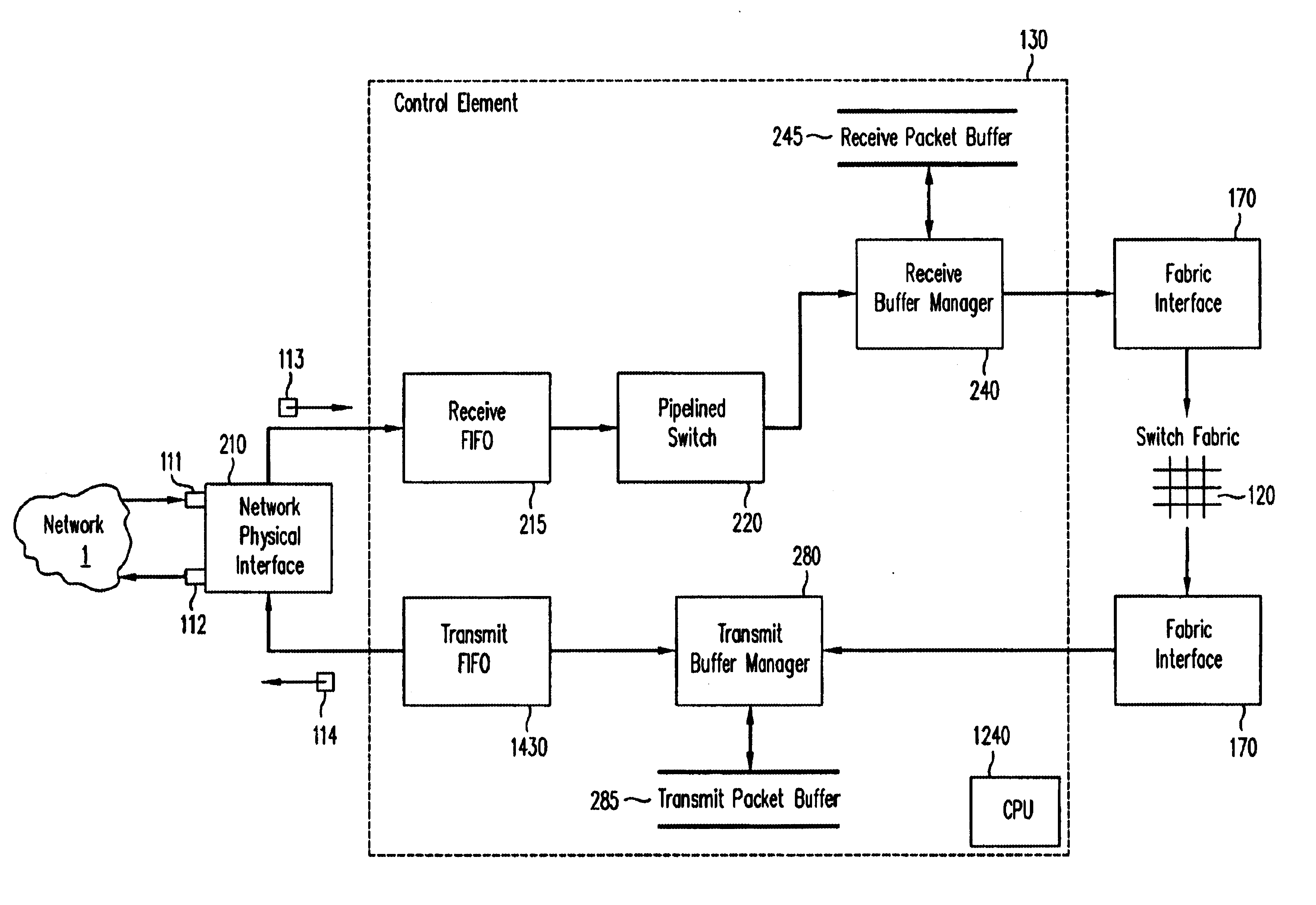
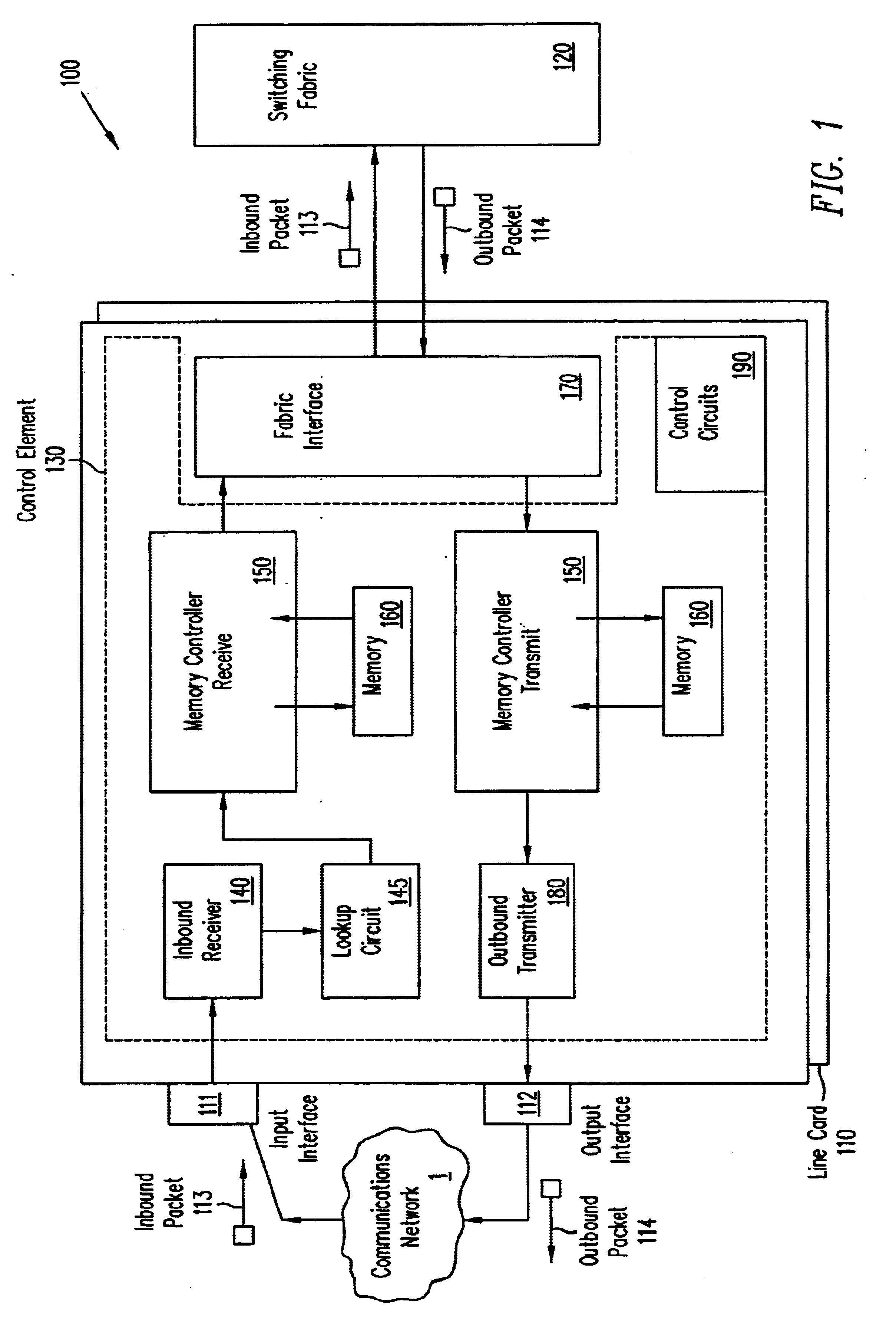
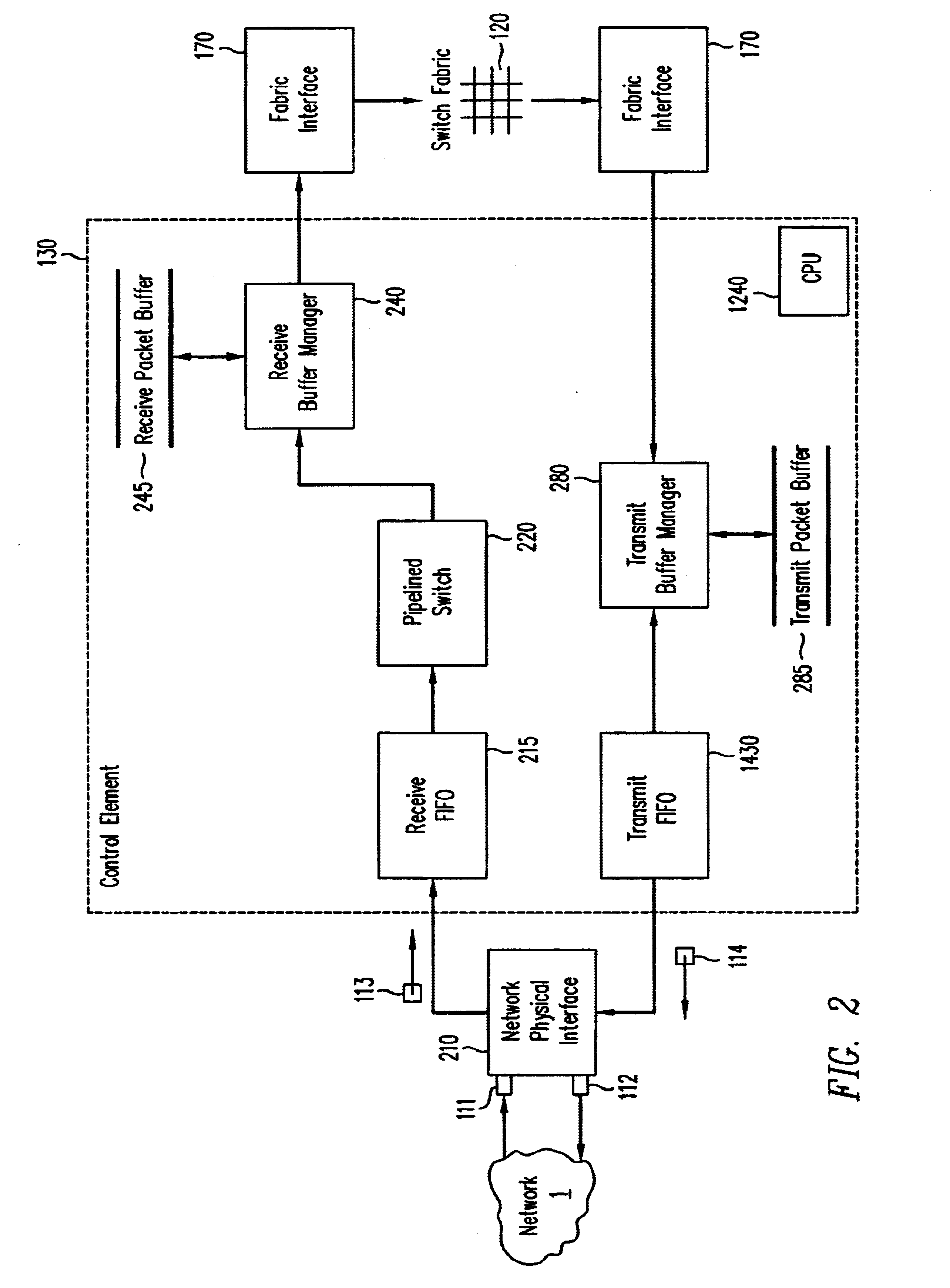
A pipelined linecard architecture for receiving, modifying, switching, buffering, queuing and dequeuing packets for transmission in a communications network. The linecard has two paths: the receive path, which carries packets into the switch device from the network, and the transmit path, which carries packets from the switch to the network. In the receive path, received packets are processed and switched in an asynchronous, multi-stage pipeline utilizing programmable data structures for fast table lookup and linked list traversal. The pipelined switch operates on several packets in parallel while determining each packet's routing destination. Once that determination is made, each packet is modified to contain new routing information as well as additional header data to help speed it through the switch. Each packet is then buffered and enqueued for transmission over the switching fabric to the linecard attached to the proper destination port. The destination linecard may be the same physical linecard as that receiving the inbound packet or a different physical linecard. The transmit path consists of a buffer/queuing circuit similar to that used in the receive path. Both enqueuing and dequeuing of packets is accomplished using CoS-based decision making apparatus and congestion avoidance and dequeue management hardware. The architecture of the present invention has the advantages of high throughput and the ability to rapidly implement new features and capabilities.

Description

1. Field of the InventionThe present invention relates to communications devices, specifically devices that enable packet forwarding and handling in communications networks.2. Description of the Related ArtIn a communications network, routing devices receive messages at one of a set of input interfaces and forward them on to one of a set of output interfaces. Users typically require that such routing devices operate as quickly as possible in order to keep up with the high rate of incoming messages. In a packet routing network, where information is transmitted in discrete chunks or "packets" of data, each packet includes a header. The header contains information used for routing the packet to an output interface and subsequent forwarding to a destination device. The packet may also be forwarded to another router for further processing and / or forwarding. Header information used for routing may include the destination address and source address for the packet. Additionally, header info...

Claims


Application Information

Patent Timeline
IPC IPC(8): H04L12/56
CPCH04L45/60H04L47/2408H04L47/2441H04L47/32H04L49/90H04L49/901H04L49/9042H04L49/9052
Inventor EPPS, GARRY P.LAOR, MICHAEL
Owner CISCO TECH INC
Why Eureka
Try Eureka