Methods and apparatus for distributing power in a computerized device

a computerized device and power distribution technology, applied in the direction of electrical apparatus casings/cabinets/drawers, coupling device connections, instruments, etc., can solve the problems of requiring a relatively large number of power conditioning components, connectors that create electromagnetic interference (emi) within the computerized device, and suffer from a variety of deficiencies. , to achieve the effect of minimizing the emission of emi and reducing the conduction and radiation of electromagnetic interferen

Inactive Publication Date: 2006-11-28
CISCO TECH INC
View PDF20 Cites 23 Cited by
  • Summary
  • Abstract
  • Description
  • Claims
  • Application Information

AI Technical Summary

Benefits of technology

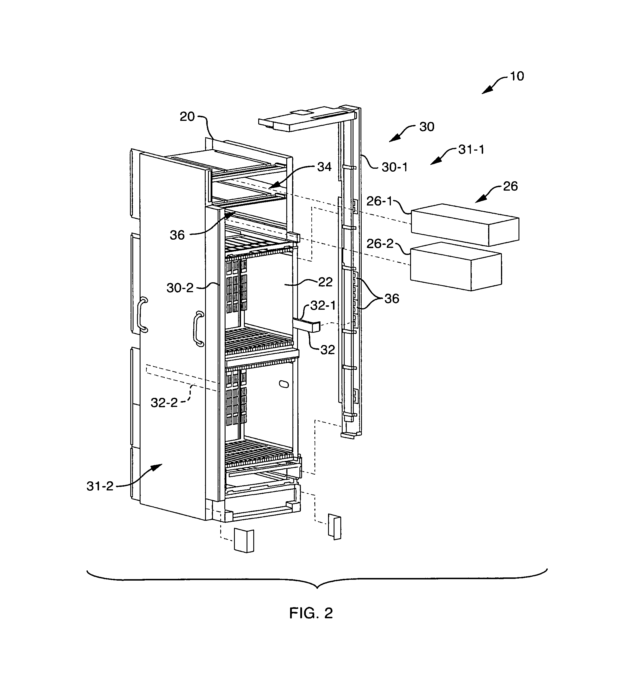
[0012]In one arrangement, a power distribution assembly includes a strap having a first end and a second end. The strap has at least one conductive plane extending from the first end of the strap to the second end of the strap where the at least one conductive plane defines a substantially rectangular cross-section along a length of the strap. The power distribution assembly also includes a first connector electrically coupled to the at least one conductive plane at the first end of the strap where the first connector is configured to couple to a bus bar of a computerized device. The power distribution assembly also includes a second connector electrically coupled to the at least one conductive plane at the second end of the strap where the second connector is configured to couple to a midplane of the computerized device. The at least one conductive plane of the strap is configured to provide a conductive pathway between the bus bar and the midplane. The substantially flat planar geometry of the power distribution assembly minimizes conduction and radiation of electromagnetic interference (EMI) by the electrical conductor during operation of the computerized device.
[0013]In one arrangement, the at least one conductive plane comprises a first conductive plane and a second conductive plane and wherein the strap comprises an insulator plane disposed between the first conductive plane and the second conductive plane. The insulator plane defining a thickness between approximately 0.004 inches and 0.006 inches, such as a thickness of approximately 0.005 inches. By separating the first and second conductive planes by a distance of approximately 0.004 inches and 0.006 inches, the second insulator plane minimizes the emission of EMI by the power distribution assembly.

Problems solved by technology

Conventional techniques for delivering power signals between a bus bar and a signal distribution plane in a computerized device, such as a Large Internet Router, suffer from a variety of deficiencies.
The circular cross-sectional geometry of the wire connector and the relatively large amount of current typically carried by the wire connector cause the connector to create electromagnetic interference (EMI) within the computerized device.
The wire connectors, however, require a relatively large number of power conditioning components to minimize EMI radiated and conducted by the wire connector.
The power conditioning components occupy a relatively large amount of space within the conventional computerized device between the bus bars and the back plane.
The because of the relatively large number of components used, the associated attachment packaging also occupies a relatively large amount of space within the chassis of the computerized device.
Because of the positioning of the midplane within the chassis of the computerized device, the computerized device typically cannot hold the relatively large number of power conditioning used to minimize EMI radiated and conducted by the wire connector coupling the midplane to the bus bars.
As such, in the case where computerized device includes a midplane, a manufacturer cannot effectively minimize EMI radiated and conducted by the wire connector.

Method used


Image

  • Methods and apparatus for distributing power in a computerized device
  • Methods and apparatus for distributing power in a computerized device
  • Methods and apparatus for distributing power in a computerized device

Examples


Embodiment Construction

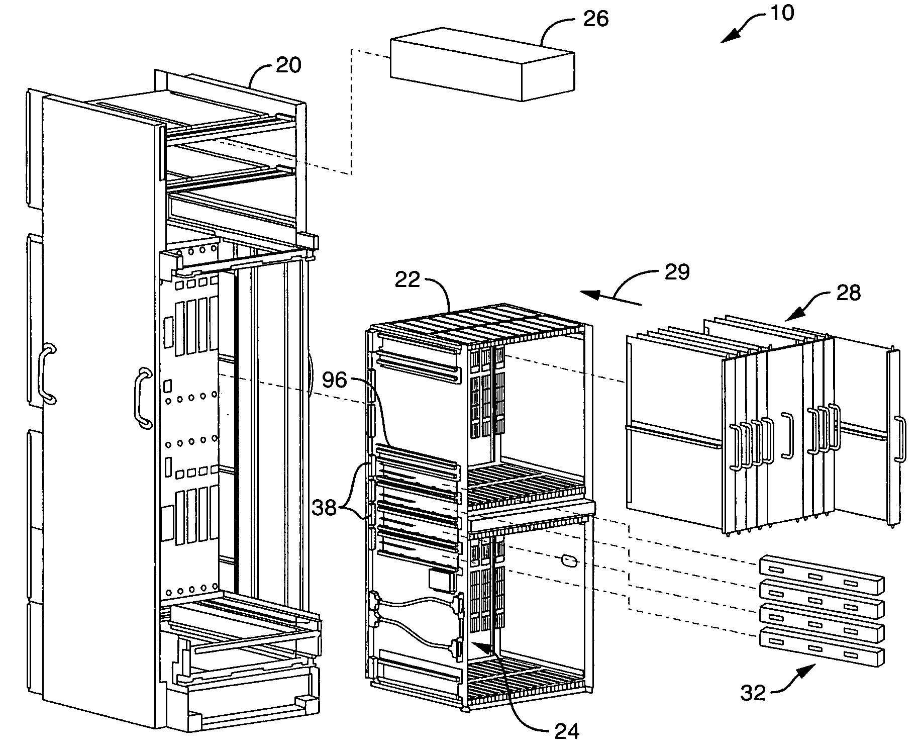
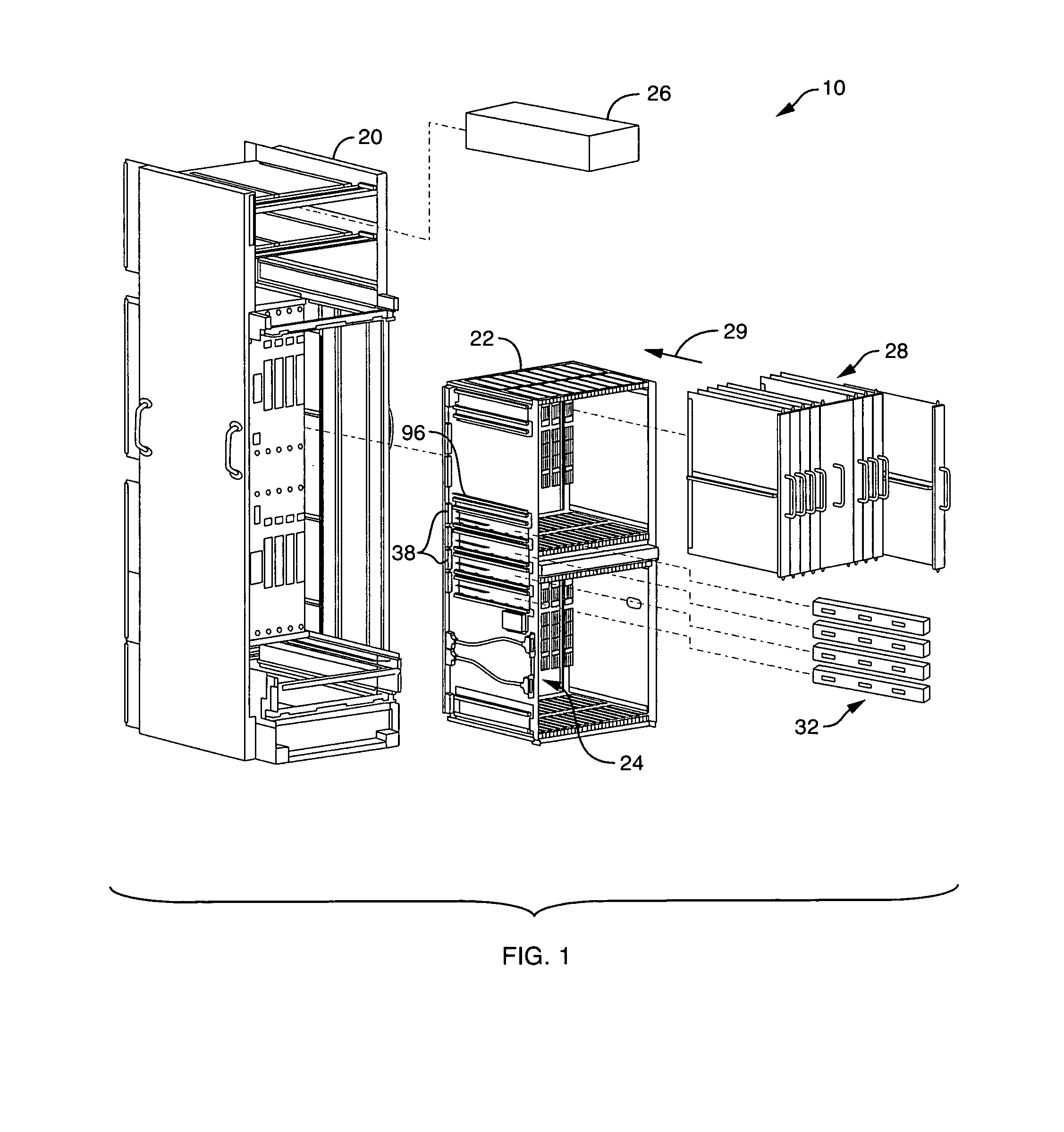
[0023]Embodiments of the present invention provide mechanisms and techniques for distributing power in a computerized device. In a computerized device requiring a relatively large amount of power during operation (e.g., between approximately 10 kW to 15 kW) at a relatively large current (e.g., between approximately 200 and 300 amperes), an electrical conductor or power distribution assembly having a substantially flat, planar geometry electrically couples a power supply, via bus bars, to a midplane of the computerized device. The substantially flat planar geometry of the power distribution assembly minimizes conduction and radiation of electromagnetic interference (EMI) by the electrical conductor during operation of the computerized device.

[0024]Additionally, the power distribution assembly includes connector ends that detachably couple to the midplane and to the power supply. The detachable connector ends allow a user to electrically and physically decouple a power supply from a m...


PUM


Abstract

In a computerized device requiring a relatively large amount of power during operation (e.g., between approximately 10 kW to 15 kW) at a relatively large current (e.g., between approximately 200 and 300 amperes), an electrical conductor or power distribution assembly having a substantially flat, planar geometry electrically couples a power supply, via bus bars, to a midplane of the computerized device. The substantially flat planar geometry of the power distribution assembly minimizes conduction and radiation of electromagnetic interference (EMI) by the electrical conductor during operation of the computerized device.

Description

BACKGROUND[0001]Certain conventional computerized devices, such as Large Internet Routers or Huge Fabric Routers (HFR's), typically include a signal distribution plane, such as a back plane, that connects to a power source via a bus bar to receive power signals from the power source. The back plane is typically configured as a circuit board, oriented at an end or back portion of a computerized device chassis, that includes jacks or connectors for plug-in cards, such as network cards. The back plane distributes the power signals to the plug-in cards and also provides connectivity among the plug-in cards for exchange of data signals. Large Internet Routers require relatively large amounts of power for operation. For example, certain Large Internet Routers require between 10 kilowatts (kW) and 15 kW of power and between 200 amperes (amps) and 300 amps to operate. Such requirements of the Large Internet Routers create difficulty in managing conducted and radiated electromagnetic interfe...

Claims


Application Information

Patent Timeline
Patent Type & Authority Patents(United States)
IPC IPC(8): H02B1/04
CPCG06F1/182G06F1/183H05K7/1492
Inventor MCLEOD, GARY
Owner CISCO TECH INC
Why Eureka
Try Eureka