
Method for segmenting 3D objects from compressed videos

a 3d object and compressed video technology, applied in the field of segmenting videos, can solve the problems of prone to quantization errors, contaminated motion vectors, and inability to obtain original picture information such as the intensity of pixel colors

Inactive Publication Date: 2006-11-28
MITSUBISHI ELECTRIC RES LAB INC
View PDF4 Cites 33 Cited by
  • Summary
  • Abstract
  • Description
  • Claims
  • Application Information

AI Technical Summary

Benefits of technology

[0024]The volumes are then sorted a high-to-low order according...

Problems solved by technology

However, in a compressed video, none of the original picture information such as the intensity of the pixel colors is available.
However, the motion vectors are often contaminated by mismatching.
In addition, the motion fields in MPEG compressed bit streams are prone to quantization errors.
However, decompressing a video to recover the original information is very time consuming, and it might not be possible to do the required analysis of the compressed video in real time, if the video first has to be decompressed.
However, the JPEG standard only deals with single still images.
Therefore, it is not possible to segment arbitrary 3D objects from still images.
Their method is not general, and does not works for videos containing an unknown number of arbitrary objects of unknown color and shape.
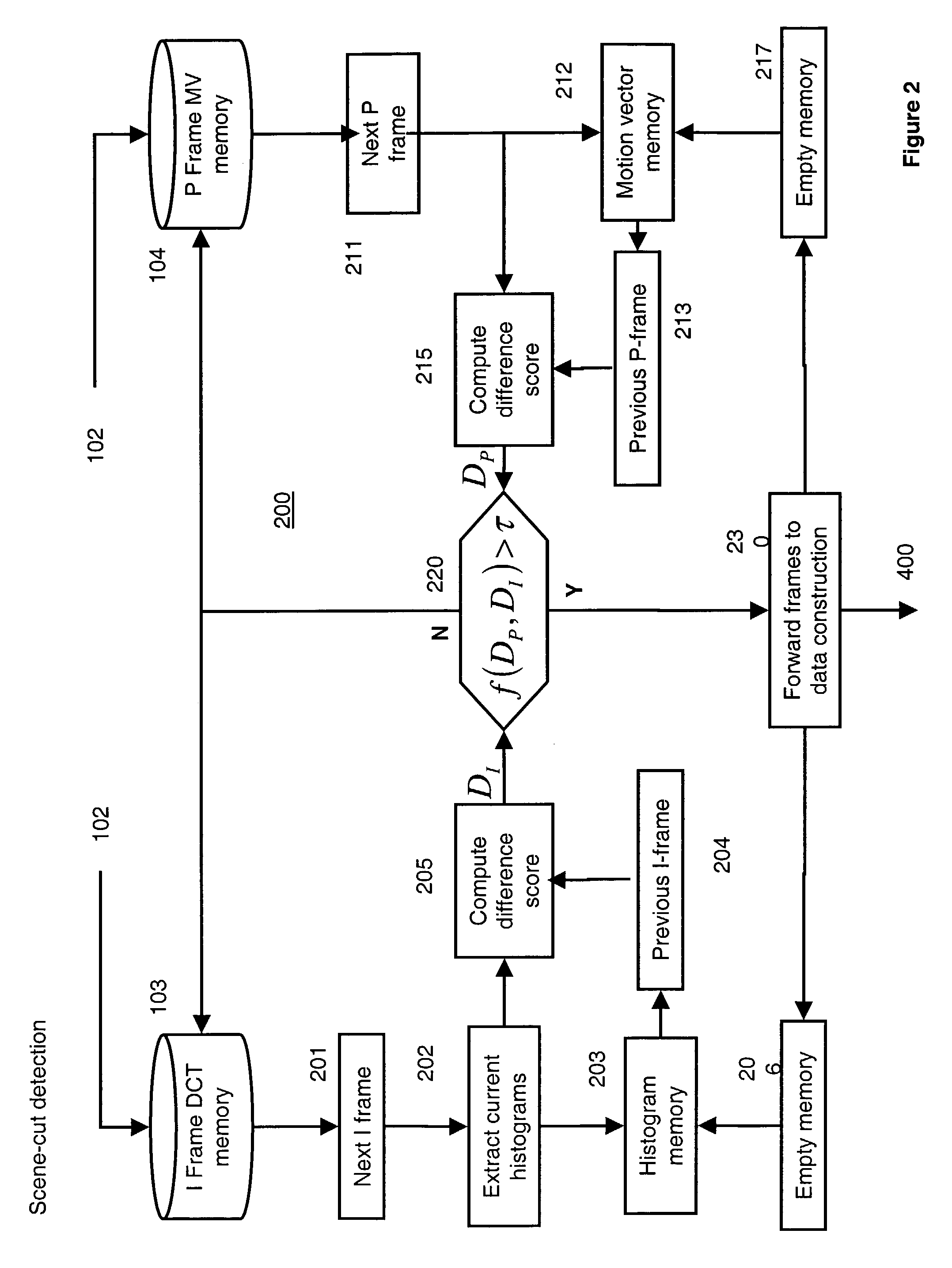
Methods based on global features, i.e., color histograms, are insensitive to motion, however, they can fail to detect scene cuts when the images before and after the shot cut have similar global features.
The methods based on spatially registered features are sensitive to moving objects, and can fail when the image is extremely slow or fast.
Although those methods are sufficient for segmenting a video into shots, they are insufficient for segmenting 3D objects from compressed videos.

Method used


Image

  • Method for segmenting 3D objects from compressed videos
  • Method for segmenting 3D objects from compressed videos
  • Method for segmenting 3D objects from compressed videos

Examples


Embodiment Construction

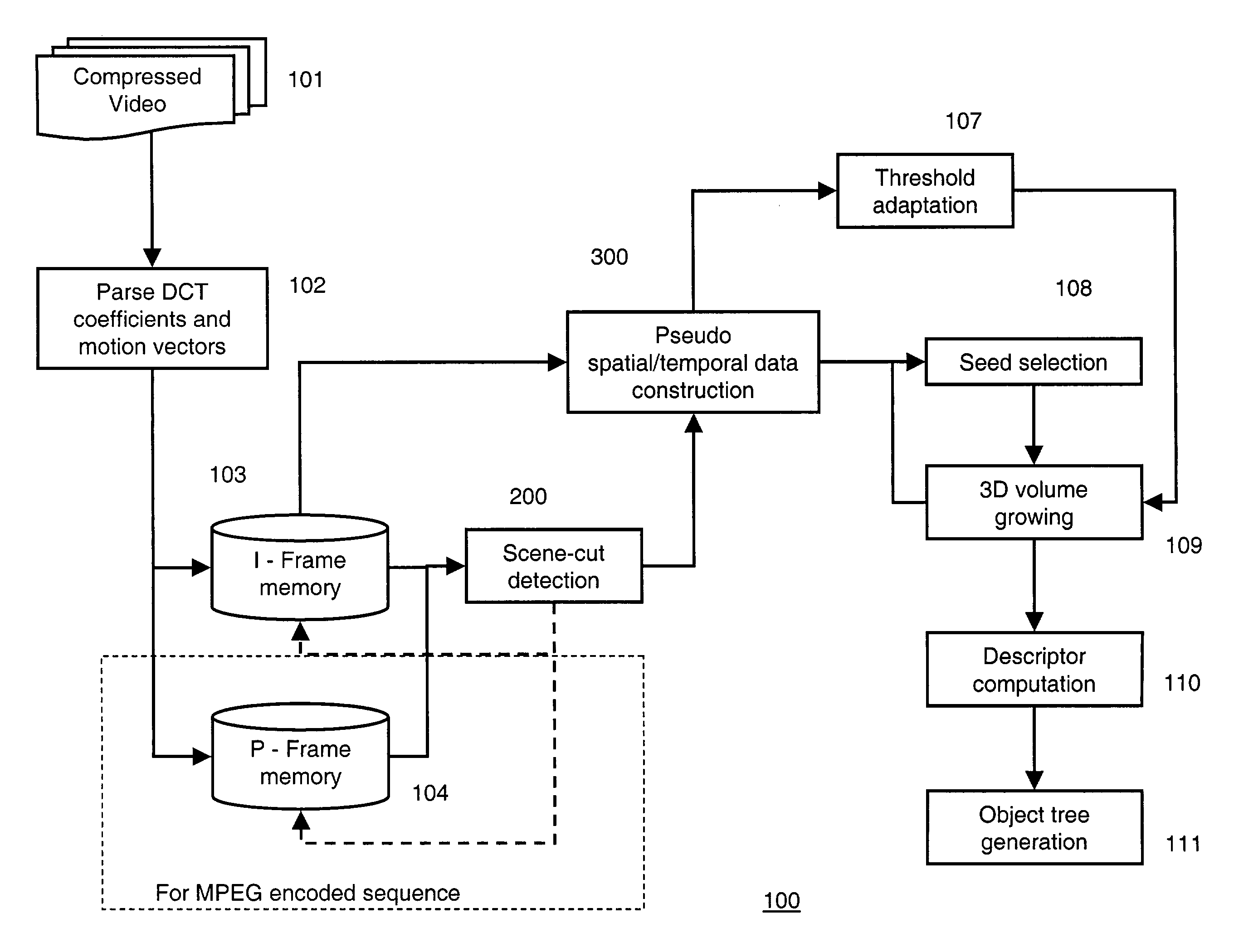
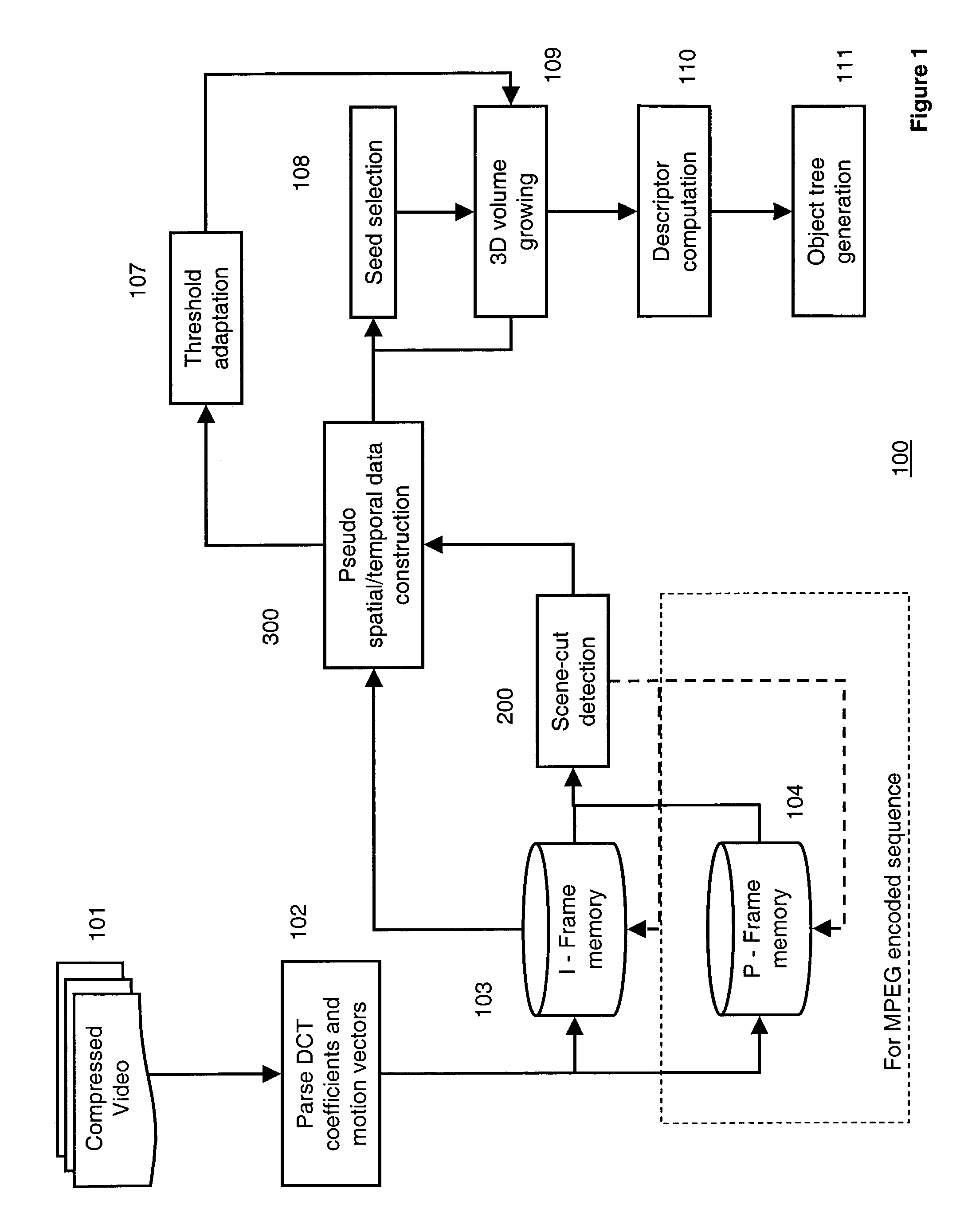
[0037]FIG. 1 shows a method 100 for segmenting 3D objects 111 from a compressed video 101 according to the invention. The video 101 includes a sequence of 2D (spatial) frames arranged in a temporal order. The compressed video is first parsed 102 to obtain the DCT coefficients and motion vectors used to compress the original pixel intensity values. The DCT coefficients that are parsed from the compressed video are stored in an I-frame memory 103 and the parsed motion vectors are stored in a P-frame memory 104.

[0038]Although the example compressed video 101 that is used to describe the invention is compressed according to the widely used MPEG standard, it should be understood that the invention can also be applied to videos compressed according to other transformations, such as, fast Fourier transform (FFT), or wavelets. Therefore, when we say ‘transformed coefficients’ we means DCT coefficients, FFT coefficients, wavelet coefficients, motion coefficients, or any other reduced set of ...


PUM


Abstract

A method segments a video into objects, without user assistance. An MPEG compressed video is converted to a structure called a pseudo spatial / temporal data using DCT coefficients and motion vectors. The compressed video is first parsed and the pseudo spatial / temporal data are formed. Seeds macro-blocks are identified using, e.g., the DCT coefficients and changes in the motion vector of macro-blocks.A video volume is “grown” around each seed macro-block using the DCT coefficients and motion distance criteria. Self-descriptors are assigned to the volume, and mutual descriptors are assigned to pairs of similar volumes. These descriptors capture motion and spatial information of the volumes. Similarity scores are determined for each possible pair-wise combination of volumes. The pair of volumes that gives the largest score is combined iteratively. In the combining stage, volumes are classified and represented in a multi-resolution coarse-to-fine hierarchy of video objects.

Description

FIELD OF THE INVENTION[0001]This invention relates generally to segmenting videos, and more particularly to segmenting 3D objects from videos.BACKGROUND OF THE INVENTION[0002]It should be possible to analyze a compressed video without having to decompress the video. Analyzing a compressed video should take less effort because there is less data. However, in a compressed video, none of the original picture information such as the intensity of the pixel colors is available. When a video is compressed according to the MPEG standards, the bit stream is converted to I-, B-, and P-frames. The I-frames store DCT information of original video frames, and the B- and P-frames store motion information and residuals after motion compensation. Although, I-frames do not store motion information, static color and texture information can be propagated to the B- and P-frames by inverse motion compensation.[0003]Compressed videos have several important characteristics useful for object analysis. Firs...

Claims


Application Information

Patent Timeline
IPC IPC(8): H04B1/66G06T5/00H04N7/30G06V10/26H04N7/12H04N7/26H04N7/32
CPCG06K9/34G06T7/0081H04N19/48H04N19/87G06T2207/10016G06T2207/20048G06T2207/20101G06T2207/20141G06T7/11G06T7/187G06V10/26
Inventor PORIKLI, FATIH M.SUN, HUIFANGDIVAKARAN, AJAY
Owner MITSUBISHI ELECTRIC RES LAB INC
Learn More