Using redundant spares to reduce storage device array rebuild time

a technology of storage device array and spares, applied in the direction of redundant data error correction, fault response, instruments, etc., can solve the problems of single point of failure time window beginning, large drives taking longer to rebuild than smaller drives, and data can be lost in the data sector, so as to reduce the probability of data being lost and reduce the time required

Inactive Publication Date: 2006-11-28
LINKEDIN
View PDF31 Cites 39 Cited by
  • Summary
  • Abstract
  • Description
  • Claims
  • Application Information

AI Technical Summary

Benefits of technology

[0011]The invention provides a number of advantages. For example, the invention advantageously reduces the probability of data being lost after the failure of a storage device in a storage device array, by reducing the time required to rebuild the data on a spare storage device. The invention also provides a number of other advantages and benefits, which should be apparent from the following description.

Problems solved by technology

The single point of failure time window begins when a storage device in a storage array fails, and continues for the time required to reliably rebuild the data that was stored on the failed storage device, on a spare storage device.
In a similar but less extreme data loss scenario, a sector of data can be lost if any surviving storage device or the spare storage device suffers an unrecoverable read error during the rebuild time.
For storage systems that have a redundancy of two, a single point of failure time window begins if two storage devices are simultaneously in a failed condition.
Generally, larger drives take longer to rebuild than smaller drives.
Many of the techniques currently employed when rebuilding data on a spare disk prolong the rebuild time.
Also, with known rebuild techniques, data is written to only a single spare disk, which can result in delay if there is an error while writing to the spare disk.
Consequently, current rebuild techniques are not completely adequate.

Method used


Image

  • Using redundant spares to reduce storage device array rebuild time
  • Using redundant spares to reduce storage device array rebuild time
  • Using redundant spares to reduce storage device array rebuild time

Examples


Embodiment Construction

[0015]The nature, objectives, and advantages of the invention will become more apparent to those skilled in the art after considering the following detailed description in connection with the accompanying drawings.

I. Hardware Components and Interconnections

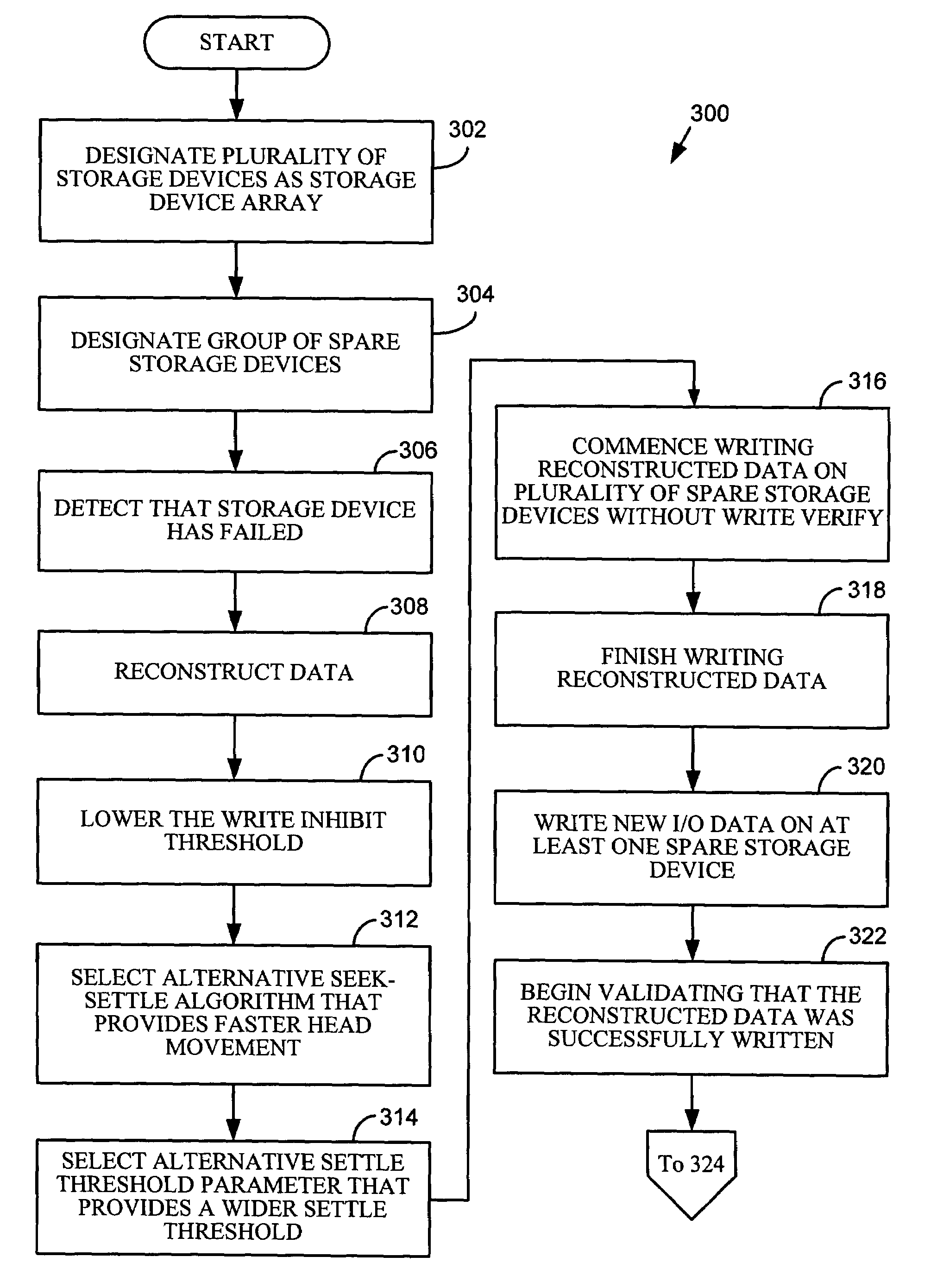
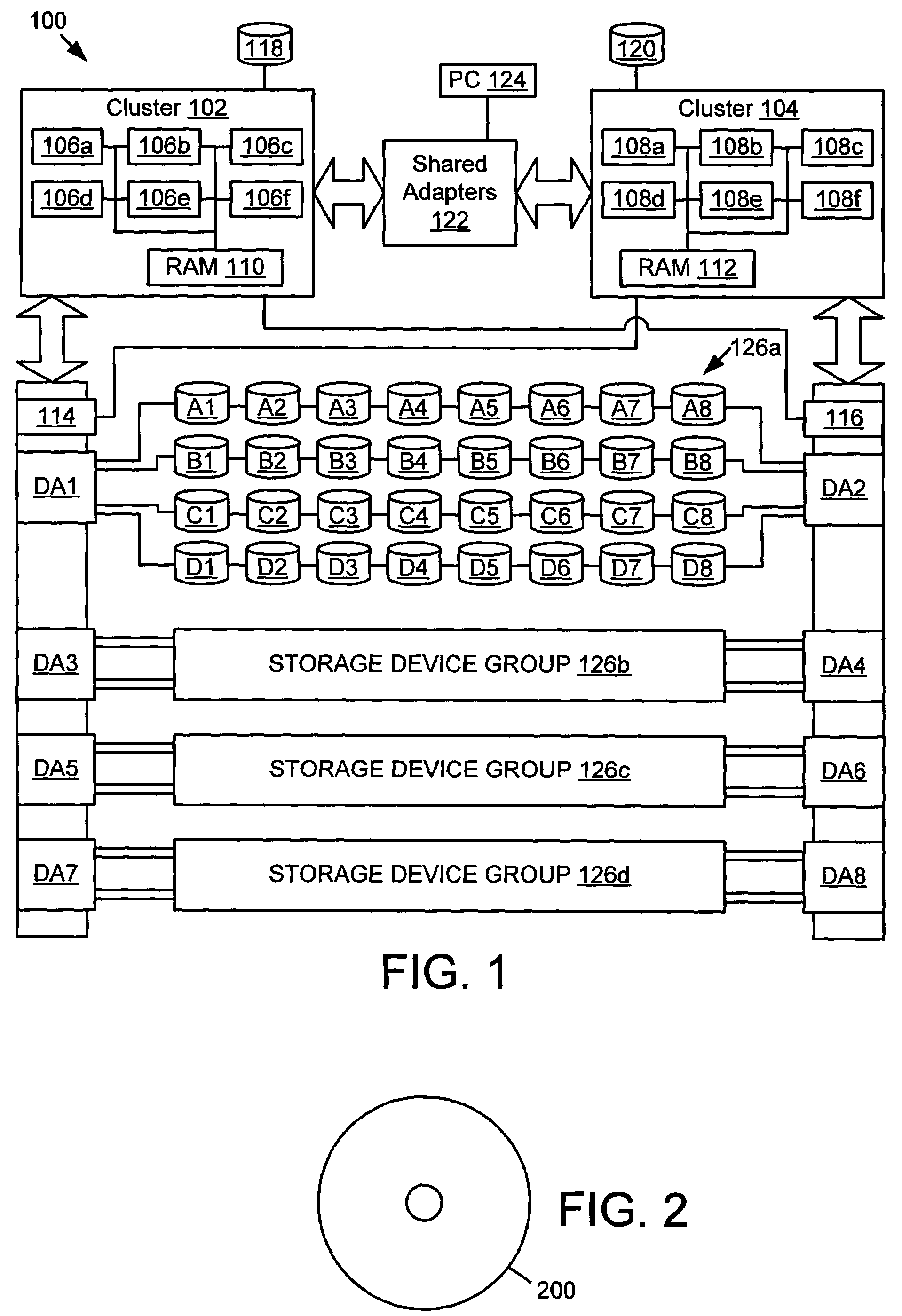
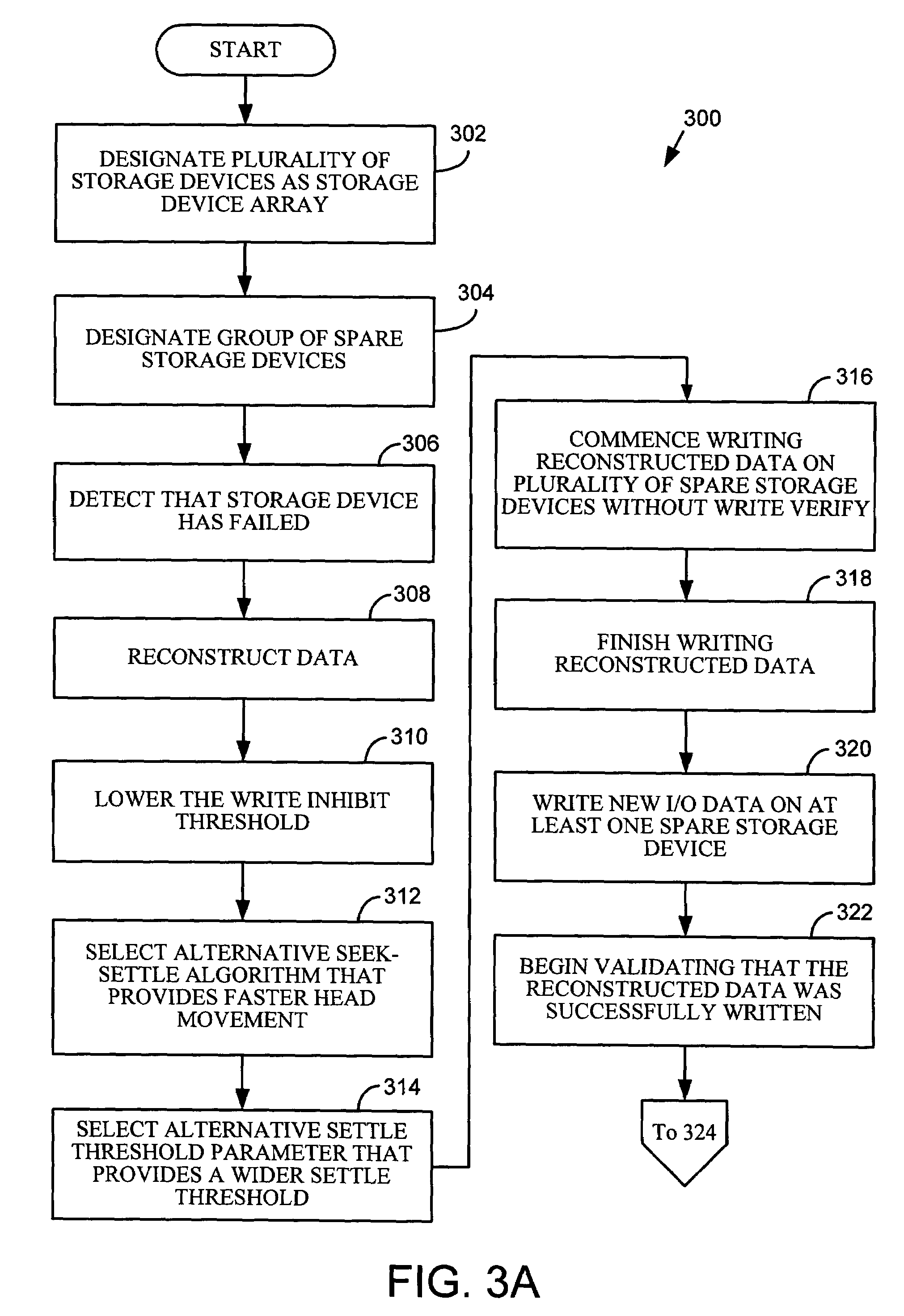
[0016]One aspect of the invention is a storage system that uses redundant spare storage devices to reduce the rebuild time when replacing a failed storage device in a storage device array. As an example, the storage system may be embodied by the hardware components and interconnections of the multi-server storage system 100 shown in FIG. 1. The storage system 100 could be implemented, for example, in a model 2105-800 Enterprise Storage Server, manufactured by International Business Machines Corporation. As an example, the storage system 100 may be used for processing and storing data for banks, governments, large retailers, or medical care providers.

[0017]The storage system 100 includes a first cluster 102, and a second cluster 10...


PUM


Abstract

A method for replacing a failed storage device in a storage device array includes detecting that the storage device has failed, and reconstructing data that was stored on the failed storage device. The method also includes commencing writing the reconstructed data on each of a plurality of spare storage devices, without verifying that the reconstructed data is successfully written, and finishing writing the reconstructed data on at least one of the spare storage devices. The method further includes beginning validating that the reconstructed data was successfully written, on each of the spare storage devices that the writing was finished on. A write complete message indicating that the reconstructed data was successfully written is received from at least one of the spare storage devices, and, a spare storage device from which a write complete message was received is accepted into the storage device array to replace the failed storage device.

Description

BACKGROUND[0001]1. Technical Field[0002]The present invention relates to replacing failed storage devices. More particularly, the invention concerns using redundant spare storage devices to reduce the rebuild time when replacing a failed storage device in a storage device array.[0003]2. Description of Related Art[0004]Important data is frequently stored in storage devices, such as hard disk drives, used in computing systems. Consequently, it is desirable to reduce the probability of data being lost if a storage device fails.[0005]Techniques that have been utilized to reduce the probability of data being lost when a storage device fails include storing parity information on another storage device, and making a duplicate copy of data on another storage device (data mirroring). If a storage device fails, parity information may be used to reconstruct the data that was on the failed storage device. If data mirroring is used, a duplicate copy of data that was on the failed storage device ...

Claims


Application Information

Patent Timeline
Patent Type & Authority Patents(United States)
IPC IPC(8): G06F11/00G06F11/10H02H3/05
CPCG06F11/1092
Inventor HAJJI, AMINE M.NIELSEN, KARL ALLEN
Owner LINKEDIN
Why Eureka
Try Eureka