Hybrid precast concrete and metal deck floor panel

a precast concrete and metal deck technology, applied in the field of precast panels, can solve the problems of long construction time, high cost, and provide for a floor system with a heavy selfweigh

Inactive Publication Date: 2006-12-05
MILLER PHILIP GLEN
View PDF19 Cites 24 Cited by
  • Summary
  • Abstract
  • Description
  • Claims
  • Application Information

AI Technical Summary

Problems solved by technology

This method, however, is costly, requires long construction times, and provides for a floor system having a heavy selfweight.
This method, however, requires the steel beams or joists to be fireproofed, the overall floor system to be relatively deep (often causi

Method used


Image

  • Hybrid precast concrete and metal deck floor panel
  • Hybrid precast concrete and metal deck floor panel
  • Hybrid precast concrete and metal deck floor panel

Examples


Embodiment Construction

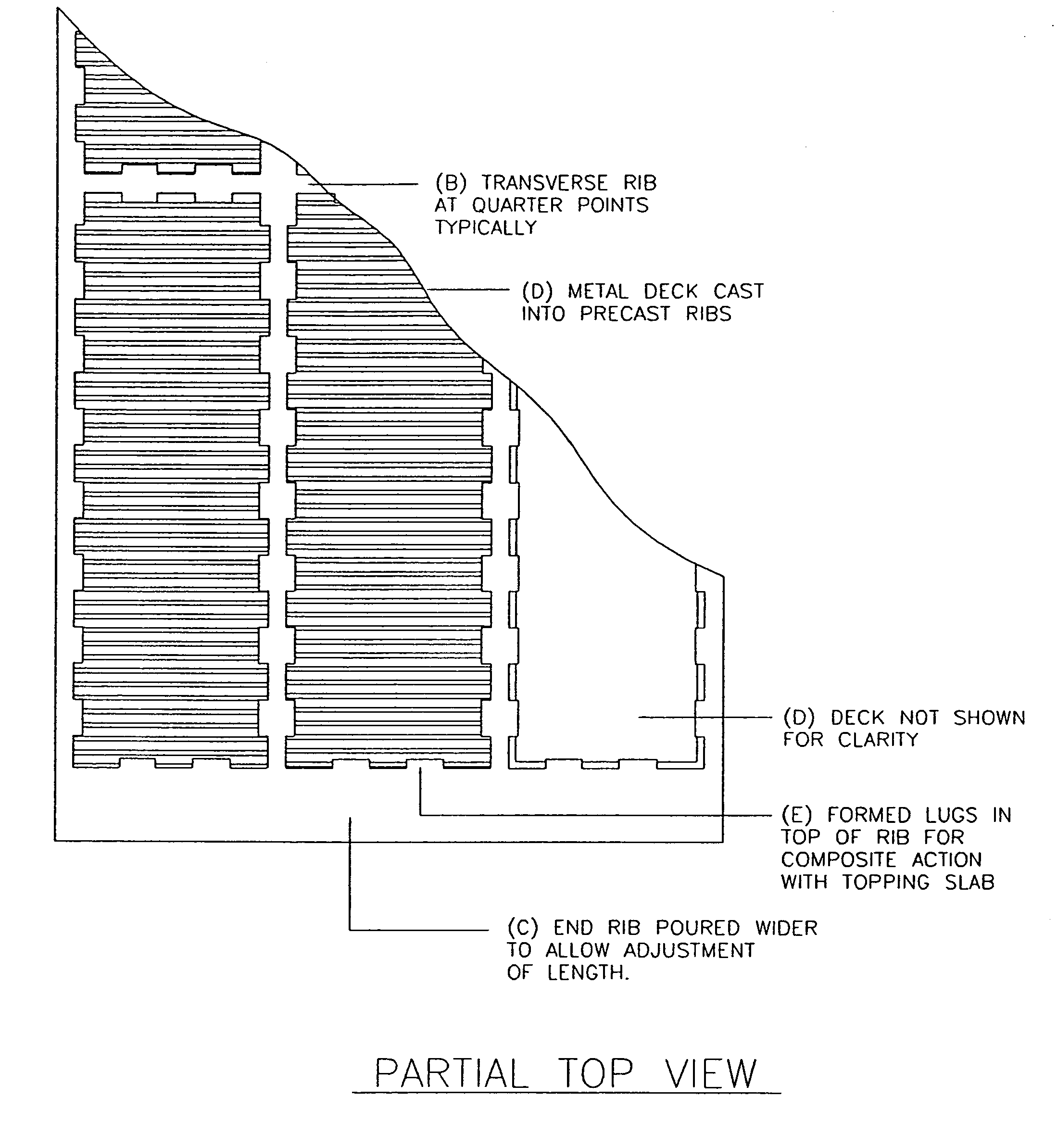
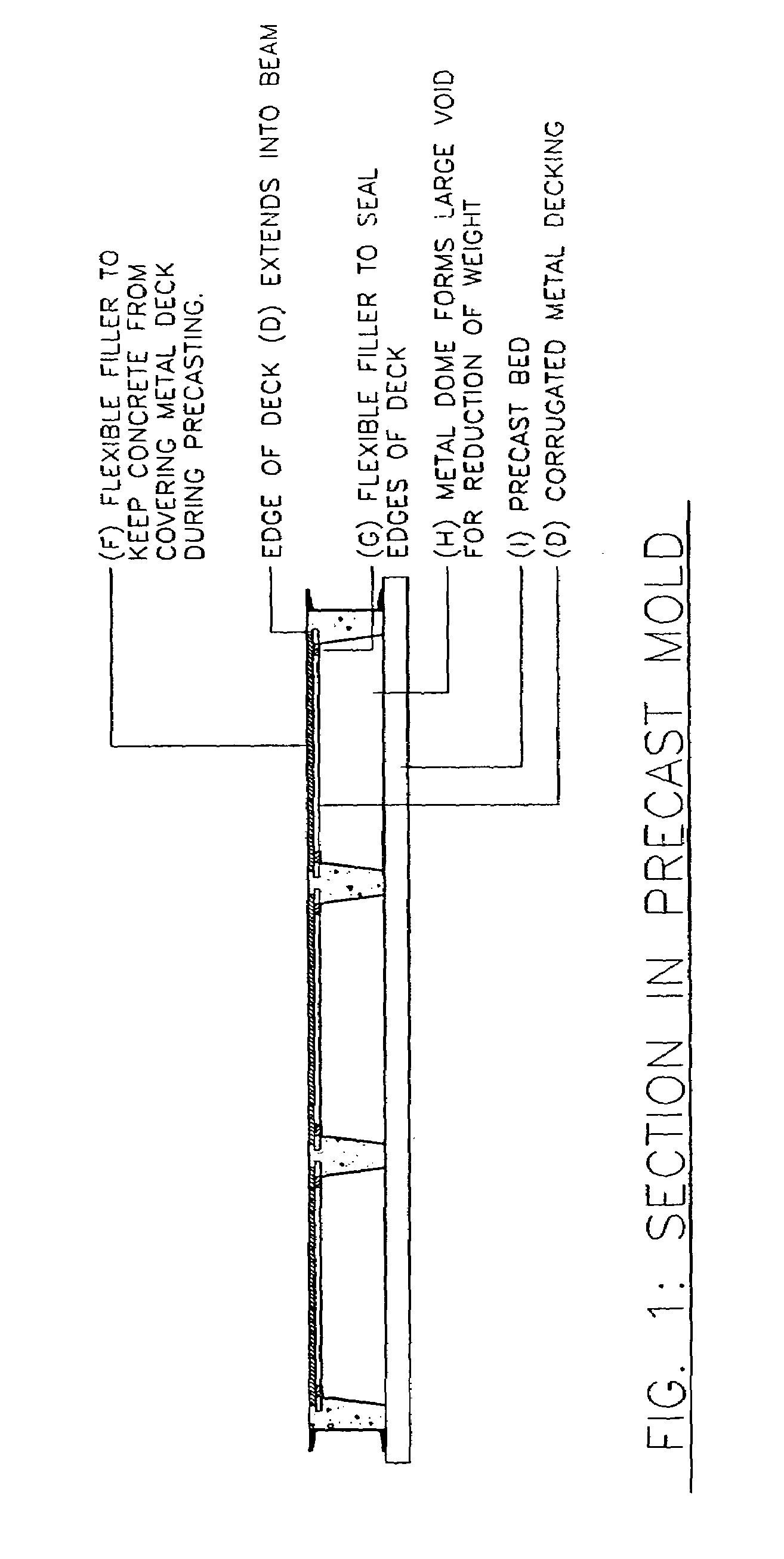
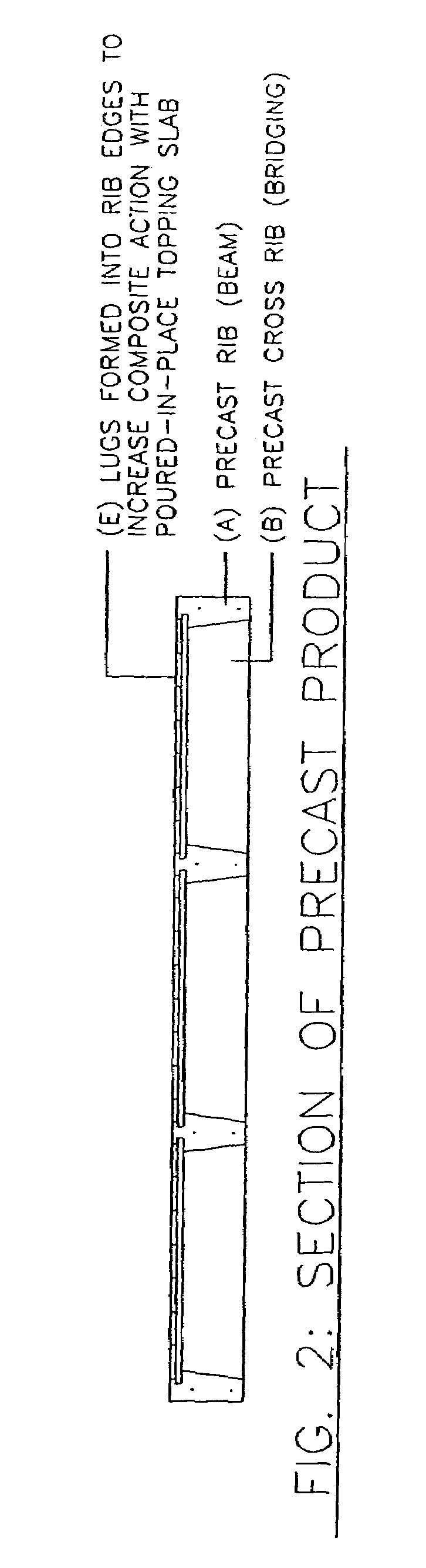
[0011]One embodiment of the present invention provides for a structural panel system (e.g., a structural floor system) that combines precast concrete structural beams (e.g., ribs) for load capacity with corrugated metal deck to provide a diaphragm and a form for a poured-in-place concrete topping slab. The embodiment combines the construction speed and offsite fabrication of precast elements with low self-weight, similar to steel structure and deck, with the relatively shallow depth and fire resistance of cast-in-place systems. The embodiment can provide for the best features of known methods, discussed above, without their respective disadvantages.

[0012]In one implementation of the present invention, a hybrid precast / steel deck panel includes structural ribs in a longitudinal direction that may provide primary spanning capacity, with minor ribs in a transverse direction that may provide lateral stability to the longitudinal ribs. These beam elements may be formed to lock small pane...


PUM


Abstract

In one implementation of the present invention, corrugated metal deck panels are attached to concrete structural beams to form a precast panel.

Description

[0001]This application claims the benefit of U.S. Provisional Application No. 60 / 326,225, filed Oct. 2, 2001.FIELD OF THE INVENTION[0002]The present invention relates in general to precast panels. In particular, the present invention relates to panels having precast concrete beams and a corrugated metal deck.BACKGROUND OF THE INVENTION[0003]It is known to use certain methods for building concrete floor slabs on the above grade floors of multi-story buildings. One method simply builds forms in place, pours the floor slab, and removes the forms after the slab reaches sufficient strength. Pans are used to form voids in the floor slab to reduce weight, while maintaining strength. This method allows the floor system to be inherently fireproof, to create thin floor sections, and to be reusable. This method, however, is costly, requires long construction times, and provides for a floor system having a heavy selfweight.[0004]Another method involves creating a structural system with steel be...

Claims


Application Information

Patent Timeline
IPC IPC(8): E04B1/00E04B5/02E04B5/04
CPCE04B5/046
Inventor MILLER, PHILIP GLEN
Owner MILLER PHILIP GLEN
Why Eureka
Try Eureka