Reduced axial movement error in a torque-sensing system

a torque sensing system and axial movement technology, applied in the field of magnetic sensors, can solve the problems of reducing increasing the tendency for torque reading errors, and affecting the accuracy of torque readings, so as to reduce the amount of torque reading errors

Inactive Publication Date: 2006-12-05
HONEYWELL INT INC
View PDF9 Cites 14 Cited by
  • Summary
  • Abstract
  • Description
  • Claims
  • Application Information

AI Technical Summary

Benefits of technology

[0008]The present invention meets shortcomings of the other torque sensing devices by arranging the magnetic torque sensors in a manner that minimizes the amount of error in the torque reading.
[0009]A magnetoelastic ring is press-fit onto a rotatable shaft to which a torque may be applied. The ring has a cylindrical shape with two magnetic bands that are magnetized in opposite directions. Alternatively, the rotatable shaft could be magnetized into bands, eliminating the need for a magnetoelastic ring. Each band has a peak magnetic field strength along the axial direction near its center. Magnetic sensors, which measure the field strength in the axial direction to determine torque, are positioned next to, but not contacting, the bands. The sensors are positioned to either side of the peak axial field strength areas of the bands, one offset from the center of one band in a first direction and the other offset from the center of the other band in a second direction opposite the first direction, thereby limiting the average change in the reading when the shaft moves in relation to the sensors. Upon axial movement of the shaft (magneto-elastic bands), one sensor measures a decrease in field strength and the other measures an increase. The two field strength measurements are combined and averaged to indicate the torque being applied to the shaft. Since one sensor reading is increasing and the other is decreasing due to axial movement of the shaft (but actual torque remains constant), the total error from the axial movement is less than typical torque sensing arrangements, resulting in a more accurate system.

Problems solved by technology

In such environments, the torque sensing devices are typically required to make low-error continuous torque measurements over extended time periods, despite severe operating conditions.
However, the shaft may have axial movement due to its floating design or the force applied.
This configuration is very susceptible to any axial, or left and right, physical movement of the shaft.
This causes a greater tendency for error in the torque reading.

Method used


Image

  • Reduced axial movement error in a torque-sensing system
  • Reduced axial movement error in a torque-sensing system
  • Reduced axial movement error in a torque-sensing system

Examples


Embodiment Construction

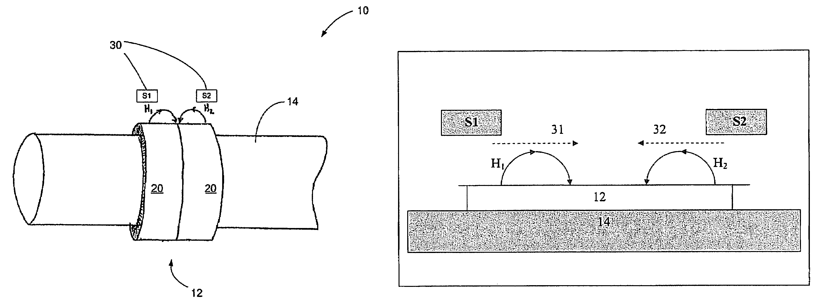
[0017]As shown in FIGS. 3 and 3A, an improved sensor arrangement 10 includes a magnetoelastic ring 12 press-fit onto a rotatable shaft 14 to which a torque may be applied. The ring 12 generally has a cylindrical shape with two magnetic bands 20 that are magnetized in opposite directions, producing magnetic fields H1 and H2. Alternatively, the rotatable shaft 14 could be magnetized into bands, eliminating the need for a magnetoelastic ring. Magnetic field sensors 30 positioned next to, but not contacting, the bands 20, can be used to measure the field strength along the axial direction, which can be converted to torque. The sensors 30 are positioned to either side of the peak axial field strength areas of the bands 20 so that when the magnetic fields H1 and H2 move (due to movement of the shaft 14 or ring 12), the average change in the reading is limited. One sensor, S1, has sensitivity in the direction of arrow 31 and is offset from the center of one band in a first direction, and t...


PUM

PropertyMeasurementUnit
torqueaaaaaaaaaa
magnetic fieldaaaaaaaaaa
field strengthaaaaaaaaaa

Abstract

An improved torque sensing arrangement includes a magnetoelastic ring on a rotatable shaft, along with two or more magnetic field sensors. The ring has at least two magnetic bands magnetized in opposite directions to produce at least two magnetic fields. Alternatively, the rotatable shaft could be magnetized into bands, eliminating the need for a magnetoelastic ring. The magnetic field sensors are positioned next to, but not contacting, the bands, and can be used to measure the field strength, which can be converted to torque. The sensors are preferably positioned to either side of the peak axial magnetic field strength areas of the bands, one offset from the center of one band in a first direction and the other offset from the center of the other band in a second direction opposite the first direction, thereby limiting the average change in the reading when the fields move under the shaft.

Description

GOVERNMENT RIGHTS[0001]The United States Government has acquired certain rights in this invention pursuant to Contract No. DAAH10-03-9-0001 awarded by the U.S. Department of the Army.BACKGROUND OF THE INVENTION[0002]1. Field of the Invention[0003]This invention relates to the field of using magnetic sensors to measure torque applied to a rotatable shaft. More particularly, the invention relates to the particular placement of magnetic torque sensors in relation to magnetic field bands to reduce the axial movement error in a torque system.[0004]2. Description of the Related Art[0005]In control of systems having rotatable drive shafts, torque and speed are the fundamental parameters of interest. The sensing and measurement of torque in an accurate, reliable, and inexpensive manner has been a primary objective of workers for several decades. Examples of applications in which inexpensive torque sensing devices are used include electric power steering systems, rotating shafts in machinery...

Claims


Application Information

Patent Timeline
Patent Type & Authority Patents(United States)
IPC IPC(8): G01L3/02G01L3/10G01L3/12G01L3/14
CPCG01L3/102
Inventor WAN, HONGFREEMAN, MICHAEL L.VON BECK, CHARLES H.
Owner HONEYWELL INT INC
Why Eureka
Try Eureka