MEMS sensor

a sensor and sensor technology, applied in the field of sensors, can solve the problems of device subject to common mode errors, imperfect self-compensation, etc., and achieve the effect of minimizing the amount of errors caused by mechanical stress

Active Publication Date: 2018-07-17
MURATA MFG CO LTD
View PDF15 Cites 0 Cited by
  • Summary
  • Abstract
  • Description
  • Claims
  • Application Information

AI Technical Summary

Benefits of technology

[0019]Embodiments of the present invention are based on the idea of anchoring more than one independent differential sensor elements of a MEMS sensor in a relatively small common anchoring area, so that the independent sensor elements experience approximately similar mechanical stress through the package of the MEMS sensor. This arrangement has an advantage that the amount of errors caused by mechanical stress is minimized. In addition, the independent sensor elements may be arranged in pairs of sensor elements, allowing double differential detection of movement. This brings further advantage by allowing, for example, removal of common mode errors, and enables self-testing of the MEMS sensor for ensuring correct operation of the device even in safety critical applications.

Problems solved by technology

However, if anchors of individual sensor elements are far from each other, self-compensation is not perfect.
The problem relating to this prior art is that although use of a single rotor enables differential detection, the device may also be subject to common mode errors that are not detectable with such single rotor mass solution.

Method used


Image

  • MEMS sensor
  • MEMS sensor
  • MEMS sensor

Examples


first embodiment

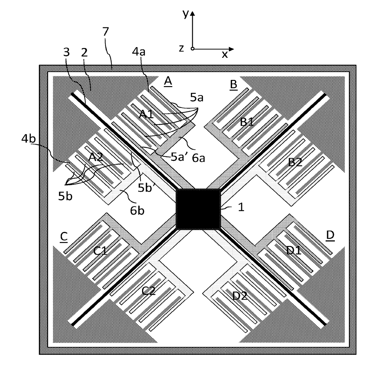
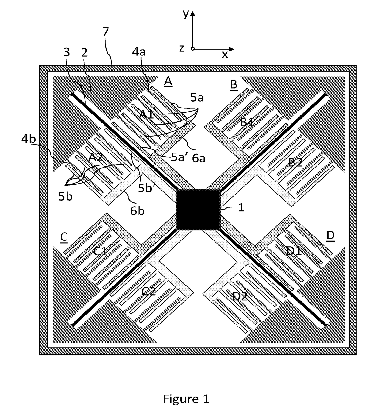
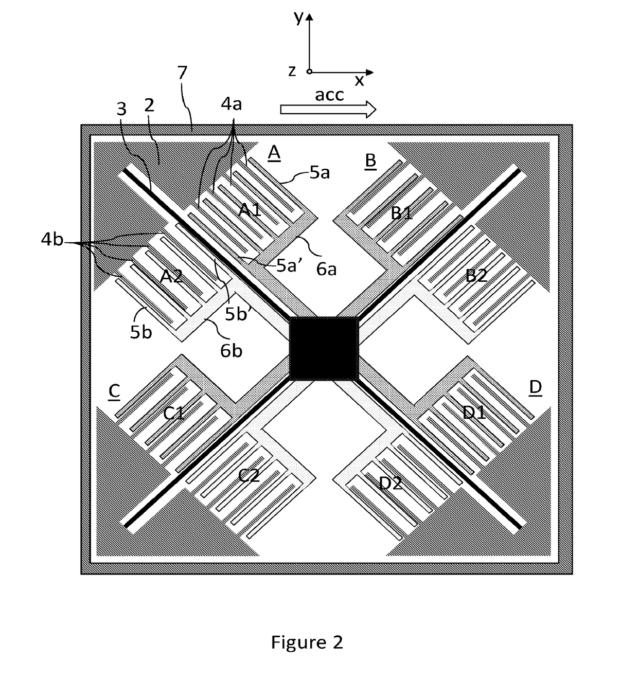
[0055]FIG. 1 presents a two-axis MEMS sensor with four differential sensor elements (A, B, C, D) each having an oblique suspension axis with respect to the intended detection axes. As defined above, with suspension axis we refer to the longitudinal direction of the spring (3) suspending the movable rotor mass (2) to an anchoring area (1). Detection axes are intended to be in x- and y-axis direction. In this example, rotor masses (2) of all four differential sensor elements (A, B, C, D) have been suspended to a common anchoring area (1) located approximately in the geometrical center (centroid) of the MEMS sensor, this way ensuring that in case any mechanical stress from package would exist, all four sensor elements (A, B, C, D) would be subject to similar stress, which may thus be compensated utilizing differential detection provided by the sensor elements (A, B, C, D). The common anchoring area (1) is a relatively small area within the total area of the MEMS sensor in xy-plane, and...

third embodiment

[0073]FIG. 6 presents the invention, in form of a one-axis MEMS sensor. This sensor is capable of detecting acceleration / inclination along x-axis. Same principle of suspending the sensor elements in one common anchor structure (1) is used as in the earlier examples: the anchoring area (1) is common to all sensor element structures, but this area may comprise one or more anchor structures disposed at or near the geometrical center of the MEMS sensor, each anchor structure supporting one or more sensor element structures. This arrangement is more traditional if compared with the first two embodiments in the way that now the direction of suspending springs (3), in other words the suspension axis is now orthogonal with the detection axis (x-axis).

[0074]This MEMS sensor has same parts as the earlier embodiments, namely a common anchoring area (1) supporting two sensor elements (A, D). Each sensor element has a rotor structure (2) flexibly suspended to one or more anchor structures locate...

sixth embodiment

[0077]FIGS. 8 and 9 illustrate a fifth and a sixth embodiment in form of a two-axis MEMS sensor. Now the detection axes are x-axis and y-axis, and each pair of sensor elements arranged to detect either of these directions differentially are suspended orthogonally in view of the respective detection axes. Suspension axis of each sensor element (A, B, C, D) is orthogonal to the detection axis of the same sensor element (A, B, C, D). Sensor elements A and D are arranged to detect acceleration / inclination in x-axis direction and sensor elements B and D are arranged to detect acceleration / inclination in y-axis direction. As in all earlier embodiments, all four sensor elements are suspended by long springs (3) to a common anchoring area (1) arranged at or in the vicinity of the geometrical center of the entire MEMS sensor. Again, arranging single common anchor structure or more than one anchor structures may be arranged at the common anchoring area (1) in the vicinity or at the geometrica...


PUM


Abstract

The present invention relates to A MEMS sensor with movable and fixed components for measuring linear acceleration. The MEMS sensor includes at least two mutually independent differential sensor elements disposed inside a common frame structure providing walls for hermetic sealing of the MEMS sensor. The mutually independent differential sensor elements are pairwise configured to perform double differential detection of linear acceleration. The MEMS sensor includes a common anchoring area to which the at least two differential sensor elements are anchored. The common anchoring area is located at the centroid of the pairwise configured differential sensor elements. A self-test capability of the MEMS sensor is also provided.

Description

BACKGROUND[0001]Field[0002]The present invention relates to MEMS sensors and especially to MEMS sensors for measuring linear acceleration as defined in independent claim 1.[0003]Description of the Related Art[0004]Micro-Electro-Mechanical Systems, or MEMS can be defined as miniaturized mechanical and electro-mechanical systems where at least some sensor elements have a mechanical functionality. MEMS structures can be applied to quickly and accurately detect very small changes in physical properties.[0005]MEMS devices convert a measured mechanical signal into an electrical signal. MEMS sensors measure the mechanical phenomenon and the electronics then process the information derived from the sensors and through some decision making capability direct the actuators to respond by e.g. moving, positioning, or regulating in order to thereby control the environment for some desired outcome or purpose. MEMS devices might be capacitive or make use of piezoelectric transduction.[0006]In an in...

Claims


Application Information

Patent Timeline
Patent Type & Authority Patents(United States)
IPC IPC(8): G01P15/125G01C9/06G01P15/18G01P15/08
CPCG01P15/125G01C9/06G01P15/18G01P2015/0817B81B2201/0235G01C2009/062B81B3/0035B81B7/0032H03H9/02275
Inventor RYTKONEN, VILLE-PEKKA
Owner MURATA MFG CO LTD
Why Eureka
Try Eureka