Common rail fuel injection system

a fuel injection system and common rail technology, applied in the direction of liquid fuel feeders, machines/engines, electric control, etc., can solve the problems of defect, defect, and defect, and achieve the effect of reducing the risk of failur

Active Publication Date: 2006-12-05
DENSO CORP
View PDF7 Cites 24 Cited by
  • Summary
  • Abstract
  • Description
  • Claims
  • Application Information

AI Technical Summary

Benefits of technology

[0015]The present invention is made in view of the above problems. It is, therefore, an object of the present invention to provide a common rail fuel injection system for an internal combustion engine, according to which it is possible to detect a malfunction of a common rail fuel pressure sensor (including an abnormal condition of outputs from the pressure sensor), even during the engine operation in which the common rail pressure is at the high pressure side.

Problems solved by technology

As a result, a defect may occur, in which an actual fuel injection amount “Qi” injected from an injector may deviate from a target fuel injection amount “Q0”.
As a result, a defect may occur, in which the actual fuel injection amount “Qi” injected from the injector would become smaller than the target fuel injection amount “Q0”, since the actual common rail fuel pressure “JP” would become lower than the target common rail fuel pressure “PC0”.
As a result, a defect may occur, in which the actual fuel injection amount “Qi” injected from the injector would become larger than the target fuel injection amount “Q0”, since the actual common rail fuel pressure “JP” would become higher than the target common rail fuel pressure “PC0”.
It is not possible in the above detection process to detect the malfunction of the common rail fuel pressure sensor, when the common rail pressure is at a high pressure side.
Accordingly, it is not possible in the above detection process to detect the malfunction of the common rail fuel pressure sensor during the engine is operating.
It may cause damages to the catalyst (e.g. a crack in the catalyst due to an excessively increased high temperature, a decrease of catalytic effect due to shortage of fuel supply), in the case that the actual fuel injection amount “Qi” is abnormally deviated from the target fuel injection amount “Q0”.

Method used


Image

  • Common rail fuel injection system
  • Common rail fuel injection system
  • Common rail fuel injection system

Examples


first embodiment

(Features of First Embodiment)

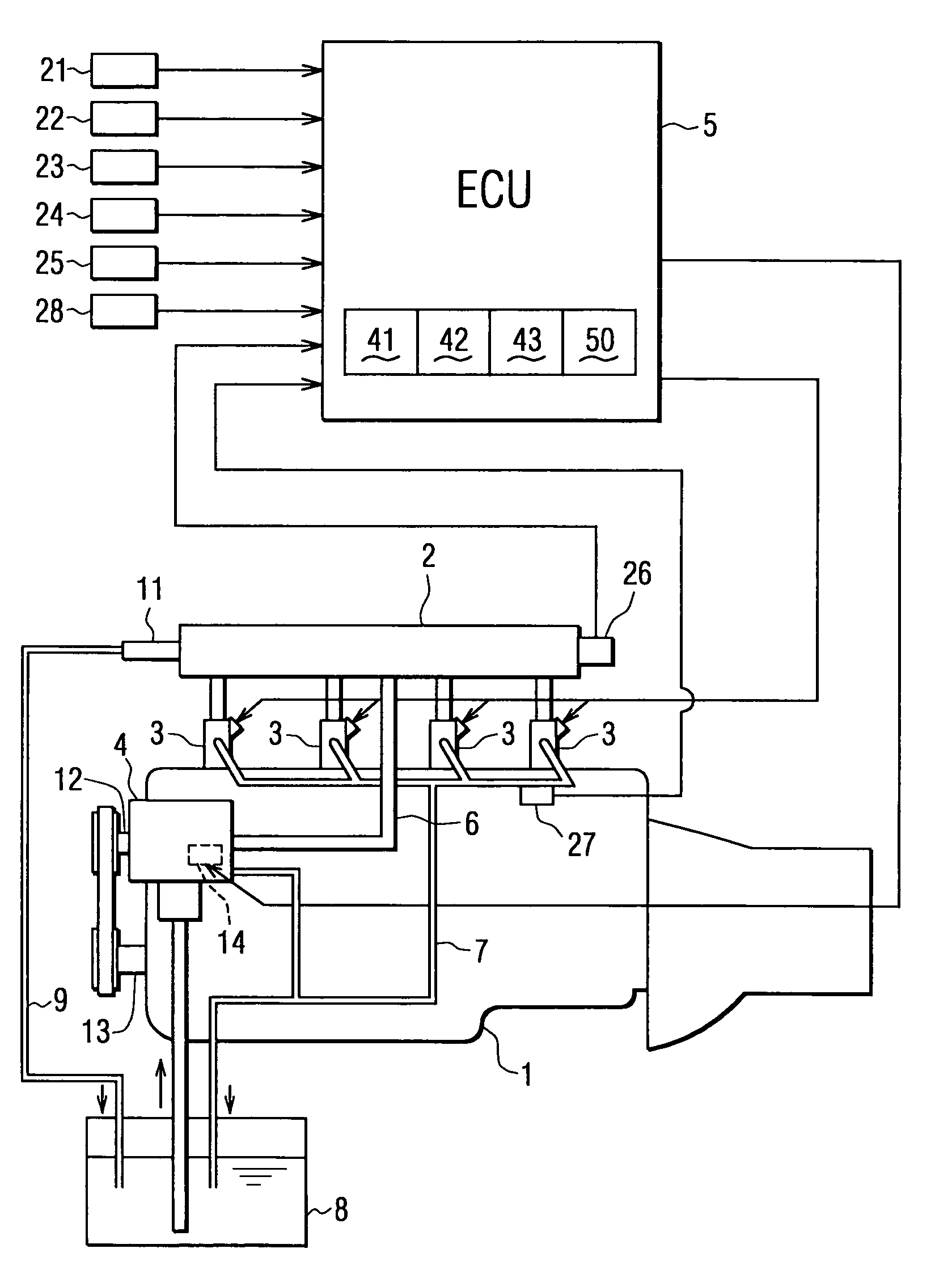
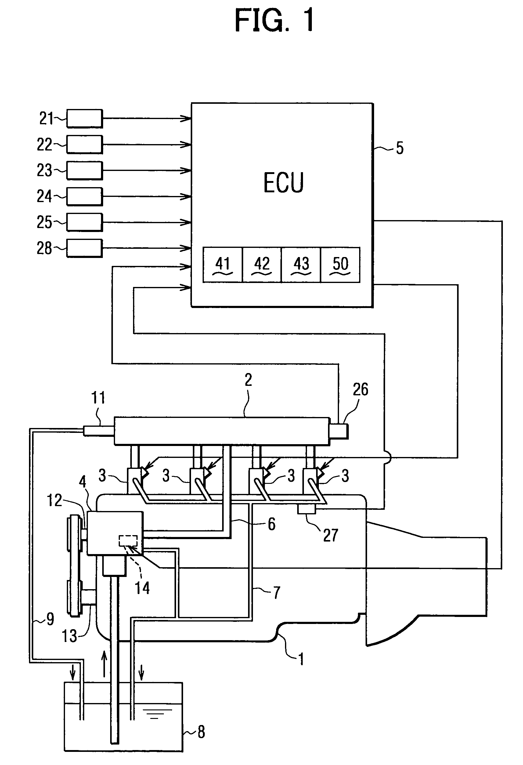
[0054]The ECU 5 further comprises a malfunction detecting means 50 for detecting whether or not any malfunction occurs in the common rail fuel pressure sensor 26 during an operation of the engine 1. The structure for this malfunction detection is explained with reference to FIGS. 3 to 6.

[0055]The malfunction detecting means 50 comprises a decreased amount presuming means 51 (which corresponds to a pressure model in FIG. 3), a first determination means 52, a combustion result presuming means 53 (which corresponds to a presumption of exhaust gas temperature in FIG. 3), a second determination means 54, a total determination means 55, and a drive means 56.

(The Decreased Amount Presuming Means 51)

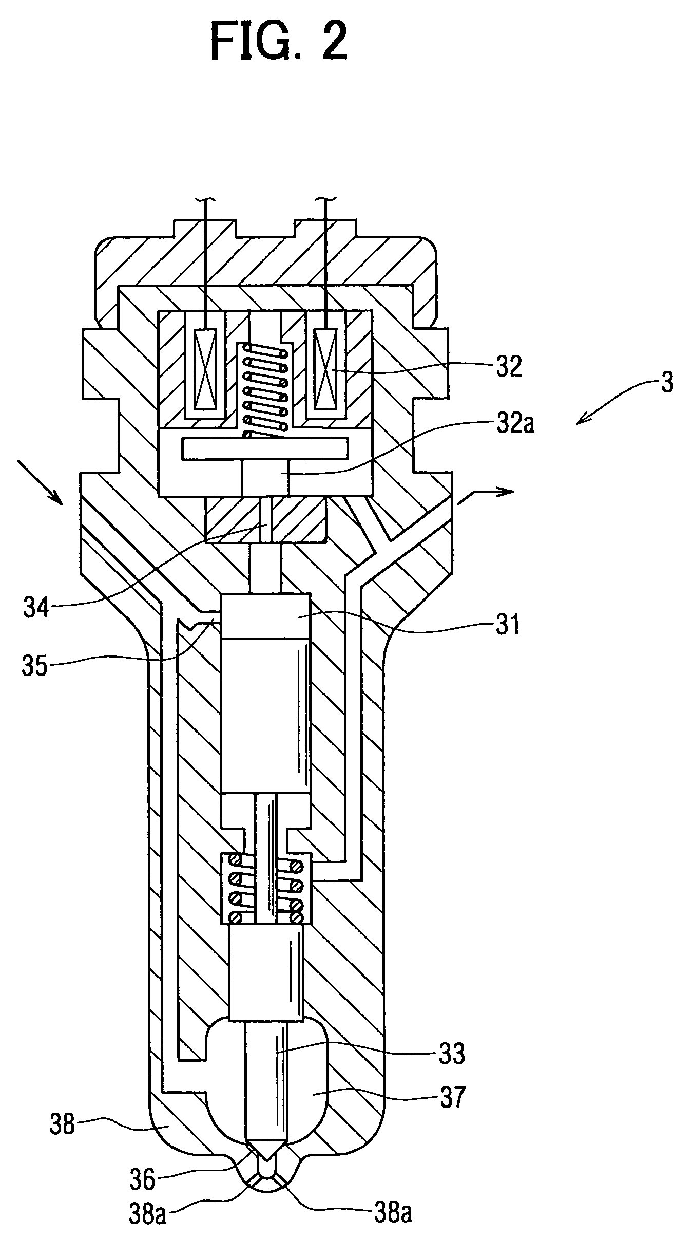
[0056]The decreased amount presuming means 51 is a program for calculating a presumed decreased amount “PC1” of the common rail pressure, which takes place as a result of fuel injections by the injectors 3.

[0057]The decreased amount of the common rail pressure cause...

first example

(First Example by Direct Comparison)

[0061]The decreased amount “PC2” is calculated by subtracting the minimum value among the detected decreased amounts “PCi” in the predetermined crank angle range (during which the fuel injection is performed at the injector 3) from the detected decreased amounts “PCi” read into the ECU 5 by the common rail fuel pressure sensor 26 at a time shortly before the fuel injection (or at the start of the fuel injection). The difference pressure “ΔPC” is calculated by subtracting the presumed decreased amount “PC1” calculated by the decreased amount presuming means 51 from the decreased amount “PC2” obtained as above.

second example

(Second Example by Indirect Comparison: Example Shown in FIG. 3)

[0062]The minimum value among the detected decreased amounts “PCi” in the predetermined crank angle range, during which the fuel injection is performed at the injector 3, is read at first. Then a presumed minimum value “YP′” of the decreased amount is calculated by subtracting the presumed decreased amount “PC1” from the detected common rail fuel pressure at the time shortly before the fuel injection (or at the start of the fuel injection). The difference pressure “ΔPC” is calculated by subtracting the presumed minimum value “YP′” of the decreased amount from the minimum value “PCi” the detected decreased amount.

[0063]When the common rail fuel pressure sensor 26 is operating in order, namely its output (the detected fuel pressure “PCi”) is in a normal condition, the output corresponds to a line A in FIG. 6A.

[0064]In the case that the output from the common rail fuel pressure sensor 26 becomes abnormal, the output would ...


PUM


Abstract

A control unit for controlling fuel pressure in a common rail comprises a pressure sensor for detecting fuel pressure in the common rail, a decreased amount presuming means for calculating a presumed decreased amount (PC1) of the common rail fuel pressure, and a first determination means for comparing the detected decreased amount (PC2) of the common rail fuel pressure with the presumed decreased amount (PC1), in order to determine whether any abnormal condition is in the outputs from the pressure sensor. Therefore, the malfunction of the pressure sensor or any abnormal conditions included in the outputs from the pressure sensor can be detected even during the engine operation.

Description

CROSS REFERENCE TO RELATED APPLICATION[0001]This application is based on Japanese Patent Application No. 2004-264246, which is filed on Sep. 10, 2004, the disclosure of which is incorporated herein by reference.FIELD OF THE INVENTION[0002]The present invention relates to a common rail fuel injection system, and more particularly to a detection system for detecting a malfunction of a pressure sensor or an abnormal output from the pressure sensor for a common rail pressure (fuel pressure) in a common rail.BACKGROUND OF THE INVENTION[0003]In a common rail fuel injection system for an internal combustion engine, a discharge fuel amount of a high pressure pump is controlled, in such a manner that a detected pressure “PCi” of a common rail fuel pressure detected by a pressure sensor becomes equal to a target pressure “PC0” for the common rail fuel pressure, which is decided depending on operational conditions of the engine.[0004]In the case that the detected pressure “PCi” of the common r...

Claims


Application Information

Patent Timeline
Patent Type & Authority Patents(United States)
IPC IPC(8): F02M69/46F02M69/54
CPCF02D41/222F02D41/3836F02D41/1446F02D2041/223F02D2041/228F02D2200/0604
Inventor UCHIYAMA, KEN
Owner DENSO CORP
Why Eureka
Try Eureka