Avia tilting-rotor convertiplane

a technology of tilting rotor and convertiplane, which is applied in the field of aircraft, can solve the problems of limiting the design of helicopters, reducing the forward speed of helicopters, and generating enormous aerodynamic drag, so as to reduce the complexity of engine/rotor mount and tilt mechanism

Inactive Publication Date: 2006-12-05
BALLEW KENNETH SYE
View PDF8 Cites 46 Cited by
  • Summary
  • Abstract
  • Description
  • Claims
  • Application Information

AI Technical Summary

Benefits of technology

[0012]The present invention solves the aforementioned problems by providing a tilt rotor aircraft having a centrally mounted tiltable engine and rotor assembly. Being mounted near the center of gravity (CG) of the craft, the engine and rotor assembly can be tilted without disturbing the CG of the aircraft. Moreover, such a central location minimizes the complexity of the engine / rotor mount and tilt mechanism.
[0013]A turbine or other type of engine (or engines) is pivotally mounted on a central frame above and between the pilot and co-pilot, who occupy separate and identical control cockpit pods on either side of the engine. Placing the engine between the pilot and copilot maintains the CG within a narrow band in both horizontal and vertical flight modes, simplifying control and handling. As the engine pivots directly on its mount, a simple, lightweight, and robust engine tilt mechanism can be provided.
[0014]Counter-rotating propellers (rotors) may be driven by the engine(s) to eliminate torque effects. The use of counter-rotating propellers and a powerful engine allows the craft to use a much smaller rotor diameter than a conventional helicopter, making storage and shipping of the craft much easier. In addition, the smaller diameter rotor means the craft is easier to handle and less likely to encounter blade strikes due to careless handling. Moreover, when traveling in horizontal flight mode, the smaller rotor provides less drag, allowing for higher horizontal speeds.

Problems solved by technology

The limitations of helicopter designs are also well known.
In particular, helicopter rotors generate an enormous amount of aerodynamic drag, which in turn limits the forward speed of a helicopter to much less than that of a conventional fixed-wing aircraft.
The V-22 Osprey has itself fallen prey to some design limitations.
The complex double tilt-rotor mechanism used by the Osprey has failed on occasion resulting in a number of mishaps.
Failure of these complex mechanisms and associated hydraulics hardware has been traced as the cause of some V-22 crashes.
The V-22 suffers from another design defect as well.
Even though the tiltable rotors are mounted on the ends of a high-wing, the craft cannot be landed in horizontal flight mode, except in cases of emergency.
If the craft is landed in horizontal flight mode, the blades of the lift / thrust props will strike the ground, destroying the props and possibly causing propeller fragments to injure the crew or bystanders.
Helicopters suffer from yet another design deficiency.
However, such swash plate and cyclic controls add complexity to the rotor and hub design, increasing unit cost, maintenance cost and decreasing reliability.
In addition, the cyclic control can be difficult to for a pilot to master and requires a different and more complicated skill set which requires extensive pilot training.
In addition, the amount of space and the weight of the tilting mechanism must be substantial, given the large arc that the engine / rotor assembly travels through.
Such an enormous rotor presents a large amount of drag when in the horizontal flight mode.
Pham also suffers from the same deficiency as the V-22 in that it cannot be landed in horizontal flight mode without destroying the main rotor blade, as it will not clear the ground in horizontal flight mode.
Providing differential thrust could require complex propeller pitch or speed control.
The unit does not appear to allow for high-speed horizontal flight.

Method used


Image

  • Avia tilting-rotor convertiplane
  • Avia tilting-rotor convertiplane
  • Avia tilting-rotor convertiplane

Examples


Embodiment Construction

[0024]The following list of design features are generalized for the purpose of describing the present invention to one of ordinary skill in the art. Like reference numerals are used to describe like components.

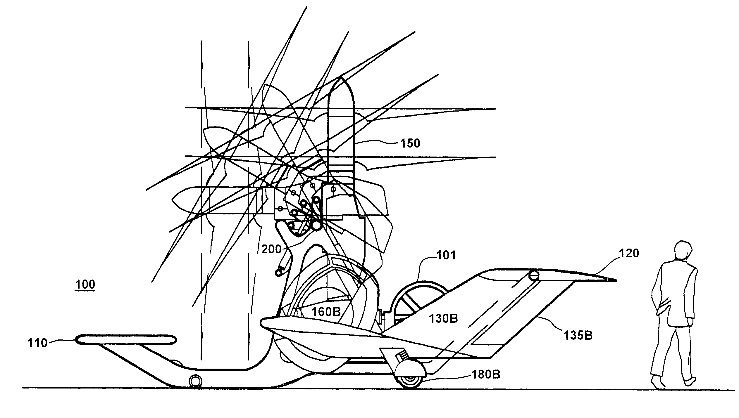
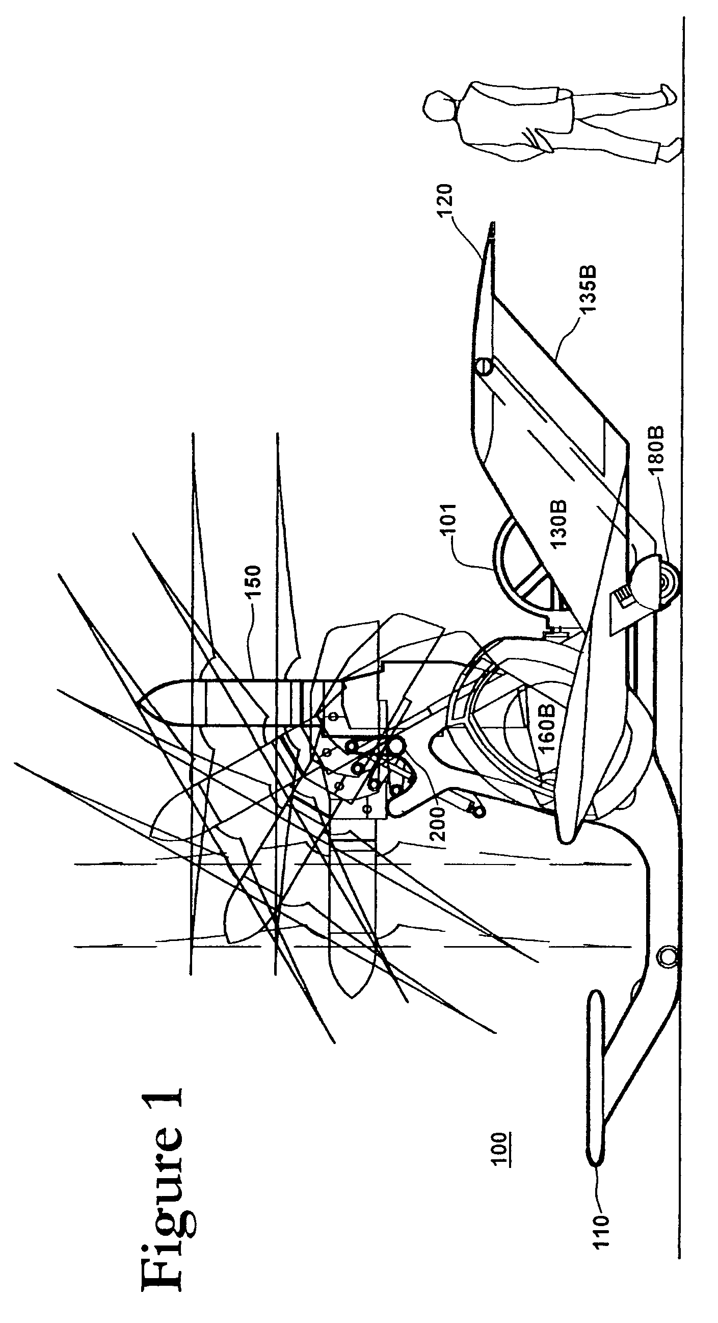
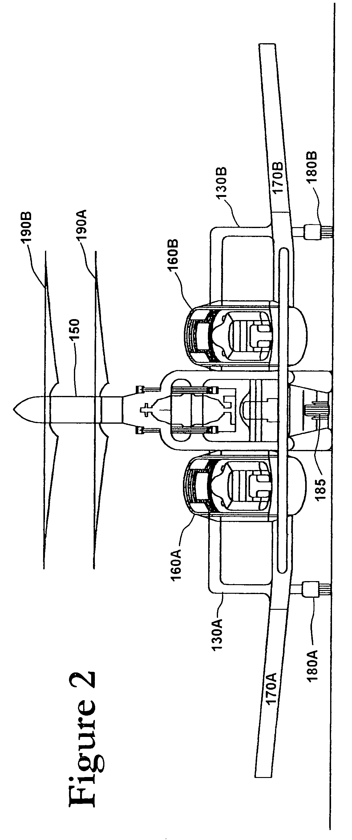
[0025]FIG. 1 is a side view of the craft 100 of the present invention illustrating the main components of the craft 100 and illustrating the travel of the tilt engine / rotor 150 from vertical to horizontal flight modes. FIG. 2 is a front view of the craft 100 of the present invention illustrating the main components of the craft 100 and illustrating the tilting engine / rotor 150 in the vertical flight mode. FIG. 3 is a top view of the craft 100 of the present invention illustrating the main components of the craft 100 and illustrating the tilting engine / rotor 150 in the vertical flight mode. FIG. 4 is a left side view of the craft 100 of the present invention illustrating the main components of the craft 100 and illustrating the tilting engine / rotor 150 in the vertical flight mo...


PUM


Abstract

The present invention provides a tilt rotor aircraft having a centrally mounted tiltable engine and rotor assembly. A turbine or other type of engine (or engines) is pivotally mounted on a central frame above and between the pilot and co-pilot, who occupy separate and identical control cockpit pods on either side of the engine. Placing the engine between the pilot and copilot maintains the CG within a narrow band in both horizontal and vertical flight modes, simplifying control and handling. Counter-rotating propellers may be driven by the engine(s) to eliminate torque effects. By mounting the engine and rotor package between and above the pilot and copilot, the rotor can be made to clear the ground, allowing the aircraft to land like an ordinary fixed-wing aircraft without damaging the propellers. Thus, the craft can be launched and landed in VTOL, HTOL, or STOL configurations, depending upon conditions and available landing and takeoff sites.

Description

CROSS REFERENCE TO RELATED APPLICATIONS[0001]The present application claims priority from Provisional U.S. Patent Application No. 60 / 519,859 filed on Nov. 14, 2003, and incorporated herein by reference.FIELD OF THE INVENTION[0002]The present invention relates to aircraft. In particular, the present invention is directed toward a tilting-rotor aircraft utilizing a centrally located tiltable powerplant fitted with counter-propellers (rotors).BACKGROUND OF THE INVENTION[0003]Helicopters and other vertical take-off and landing craft (VTOL) are known in the art. The limitations of helicopter designs are also well known. In particular, helicopter rotors generate an enormous amount of aerodynamic drag, which in turn limits the forward speed of a helicopter to much less than that of a conventional fixed-wing aircraft.[0004]Many attempts have been made to overcome this particular deficiency of helicopter design. Probably the most notable attempt has been the limited production of the Bell V-...

Claims


Application Information

Patent Timeline
Patent Type & Authority Patents(United States)
IPC IPC(8): B64C27/22B64C27/10B64C27/28B64C29/00
CPCB64C27/10B64C27/28B64C29/0033
Inventor BALLEW, KENNETH SYE
Owner BALLEW KENNETH SYE
Why Eureka
Try Eureka