Lock with internal retainer

a technology of internal retainers and locks, which is applied in the direction of rod connections, couplings, drags, etc., can solve the problems of interfering with the removal of the lock body

Inactive Publication Date: 2006-12-05
ESCO GRP LLC
View PDF36 Cites 52 Cited by
  • Summary
  • Abstract
  • Description
  • Claims
  • Application Information

AI Technical Summary

Benefits of technology

[0012]The various aspects of the invention provide several advantages. First, the invention substantially reduces, if not eliminates, the problem of soil fines interfering with removal of the lock. The lock does not require displacement of soil fines within the opening in the wear member in order to be removed. To remove the lock, the retainer is removed from the lock body, which then allows the lock body to be rotated or pulled out of the opening in the wear member. The lock body travels along a...

Problems solved by technology

The retainer is at least partially received within the channel, so that at least a portion of the reta...

Method used


Image

  • Lock with internal retainer
  • Lock with internal retainer
  • Lock with internal retainer

Examples


Embodiment Construction

[0029]The present invention relates to a locking assembly for securing two members with respect to one another, such as a moveable or replaceable wear member with respect to a fixed base member. The present invention finds application in many different types of situations in which it is desired to couple or secure two members with respect to one another. For example, the present invention may be used to secure wear members to excavating or mining equipment, such as a wear member to the exterior of a bucket, wear members to stationary equipment, points to adapters, etc.

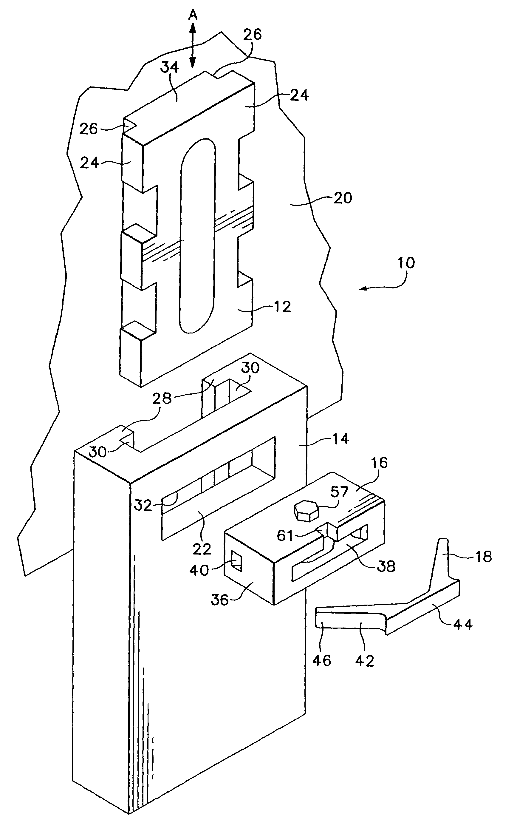
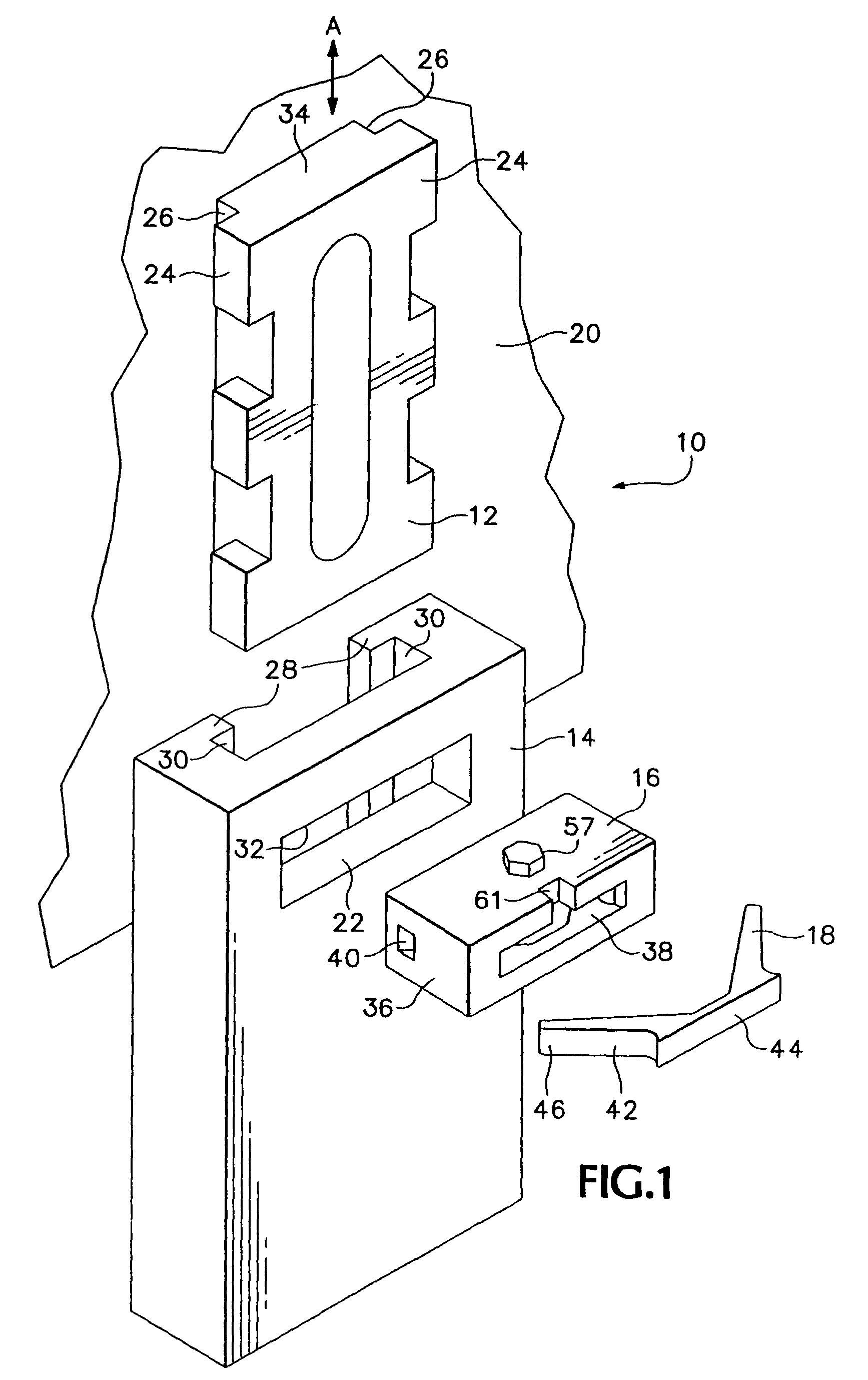
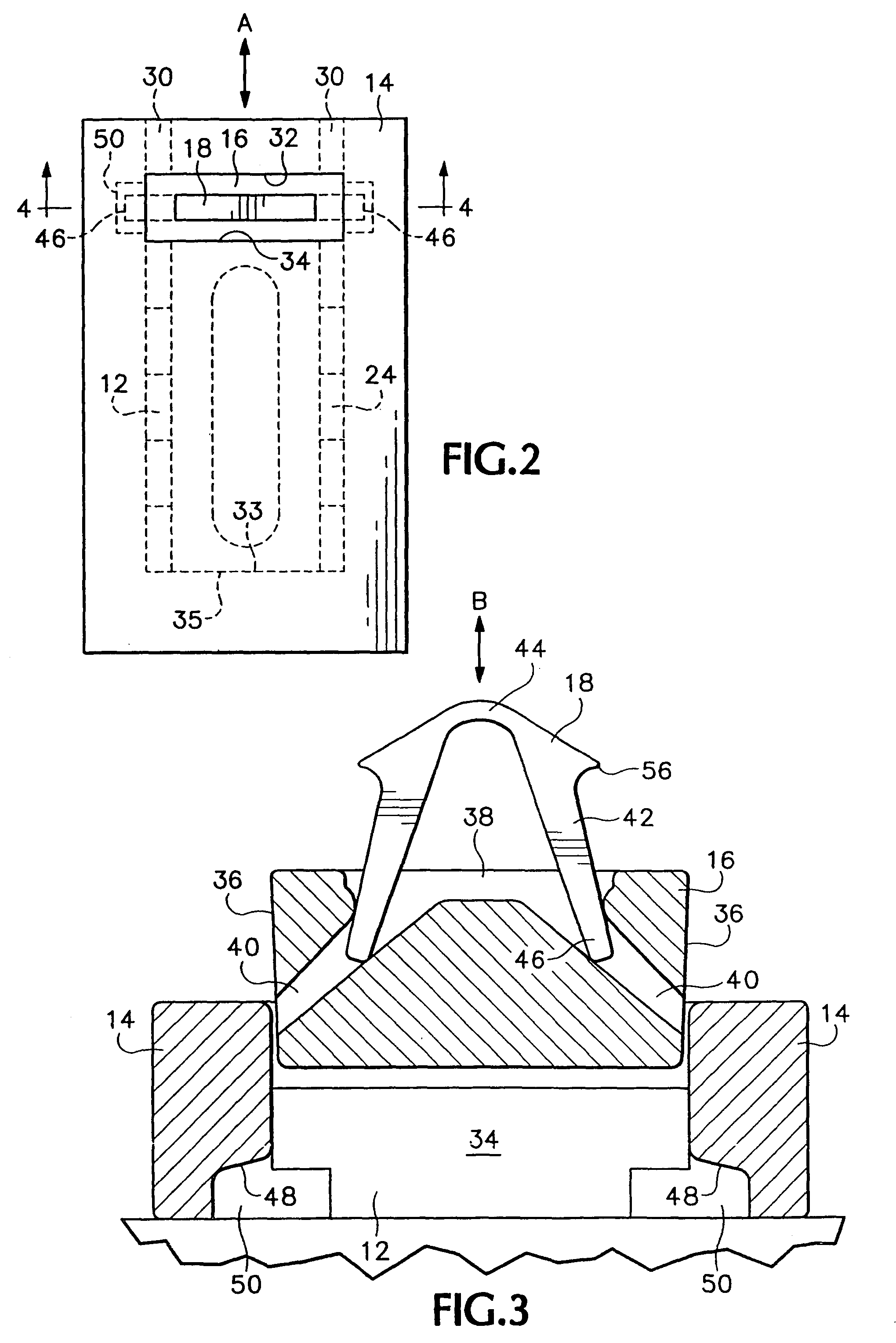
[0030]Referring now to the drawings, wherein like numerals refer to like elements, FIG. 1 shows an exemplary assembly 10 comprising a base member 12, a wear member 14, and a lock comprising a lock body 16 and a retainer 18. The base member 12 is attached to the exterior of the surface 20 to be protected, such as an exterior surface of a dragline bucket or other earthmoving or excavating equipment. The wear member 14 sl...


PUM


Abstract

A locking assembly has two members which are moveable into coupling engagement with one another. The two members have lock engaging walls, and one of the members has an opening between the lock engaging walls for receiving a lock. The lock comprises a lock body and a retainer. The lock body has a channel for receiving a portion of the retainer. An end of the retainer extends underneath a retainer engaging wall, thus resisting movement of the lock out of the opening.

Description

RELATED APPLICATIONS[0001]This application is a continuation of U.S. patent application Ser. No. 09 / 900,834, filed Jul. 6, 2001, now abandoned.BACKGROUND OF THE INVENTION[0002]The present invention relates to a lock assembly for securing two components together, and more particularly, to a lock comprising a lock body and a retainer housed within the lock body to retain the lock body in a locked condition.[0003]It is often desired to secure two members together. For example, earthmoving and excavating equipment often employ wear members to protect the equipment from abrasion and wear encountered during use. The wear members are preferably removably attached to the equipment with a locking assembly, so that a wear member may be removed and replaced as needed. An example of such a wear member and associated locking assembly is disclosed in Jones, et. al, U.S. Pat. No. 5,241,765.[0004]The continuing problem is to provide a locking assembly which securely locks the wear member to the equ...

Claims


Application Information

Patent Timeline
IPC IPC(8): F16B21/16E02F9/28F16B13/08
CPCE02F9/2841E02F9/2883F16B13/085Y10T403/7064Y10T403/585Y10T403/587Y10T403/583F16B2200/69F16B2200/71
Inventor LIAN, AARON B.CARPENTER, CHRISTOPHER M.HUNGERFORD, DECEASED, EMORY D.HUNGERFORD, LEGAL REPRESENTATIVE, LORRAINE R.MORRIS, RAY J.
Owner ESCO GRP LLC
Why Eureka
Try Eureka