Cam bar centering mechanism

a technology of centering mechanism and cam bar, which is applied in the direction of yielding coupling, coupling, rotary machine parts, etc., can solve the problems of difficult design of constant velocity universal joints capable of operating at high angles and packaging robust internal supporting devices, and achieve low drive-line disturbance, high torque load, and high speed

Inactive Publication Date: 2006-12-05
UNIVERSAL DRIVE TECH
View PDF20 Cites 4 Cited by
  • Summary
  • Abstract
  • Description
  • Claims
  • Application Information

AI Technical Summary

Benefits of technology

[0010]The apparatus of the present invention solves the problems confronted in the art in a simple and straightforward manner. What is provided is a cam rod centering mechanism. In a preferred embodiment of the present invention, the cam rod centering mechanism comprises a cam centering mechanism for universal joints. The invention is advantageous because it supports the universal joint with robust components in a relatively small package while allowing the universal joint to operate at high angles of misalignment from 0° through 90° while transmitting high torque loads at high speeds with low drive-line disturbances.
[0011]The self supported universal joints of the present invention are capable of operating at constant velocity at high angles, high speeds and high torque loads and provide design engineers with the following options: higher power transfer capability to driven members (e.g. wheels, power takeoffs); more options in drive-line placement; engines can be run at higher r.p.m. resulting in greater fuel economy; and tighter turning radiuses for vehicles.

Problems solved by technology

Universal joint designers have found it difficult to design constant velocity universal joints capable of operating at high angles, high speeds and high loads simultaneously, due to the limitations of existing constant velocity universal joint centering and supporting devices.
This is due to the difficulty in packaging robust internal supporting devices that utilize rolling elements that are capable of operating at typical driveline speeds.

Method used


Image

  • Cam bar centering mechanism
  • Cam bar centering mechanism
  • Cam bar centering mechanism

Examples


Embodiment Construction

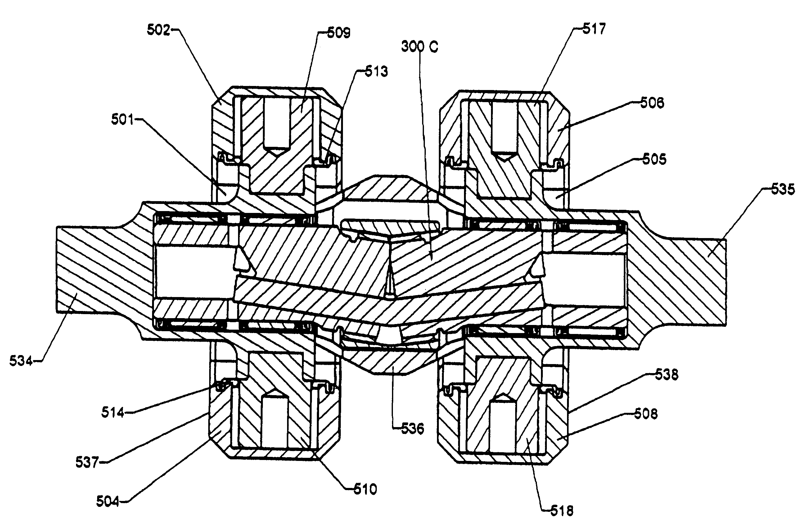
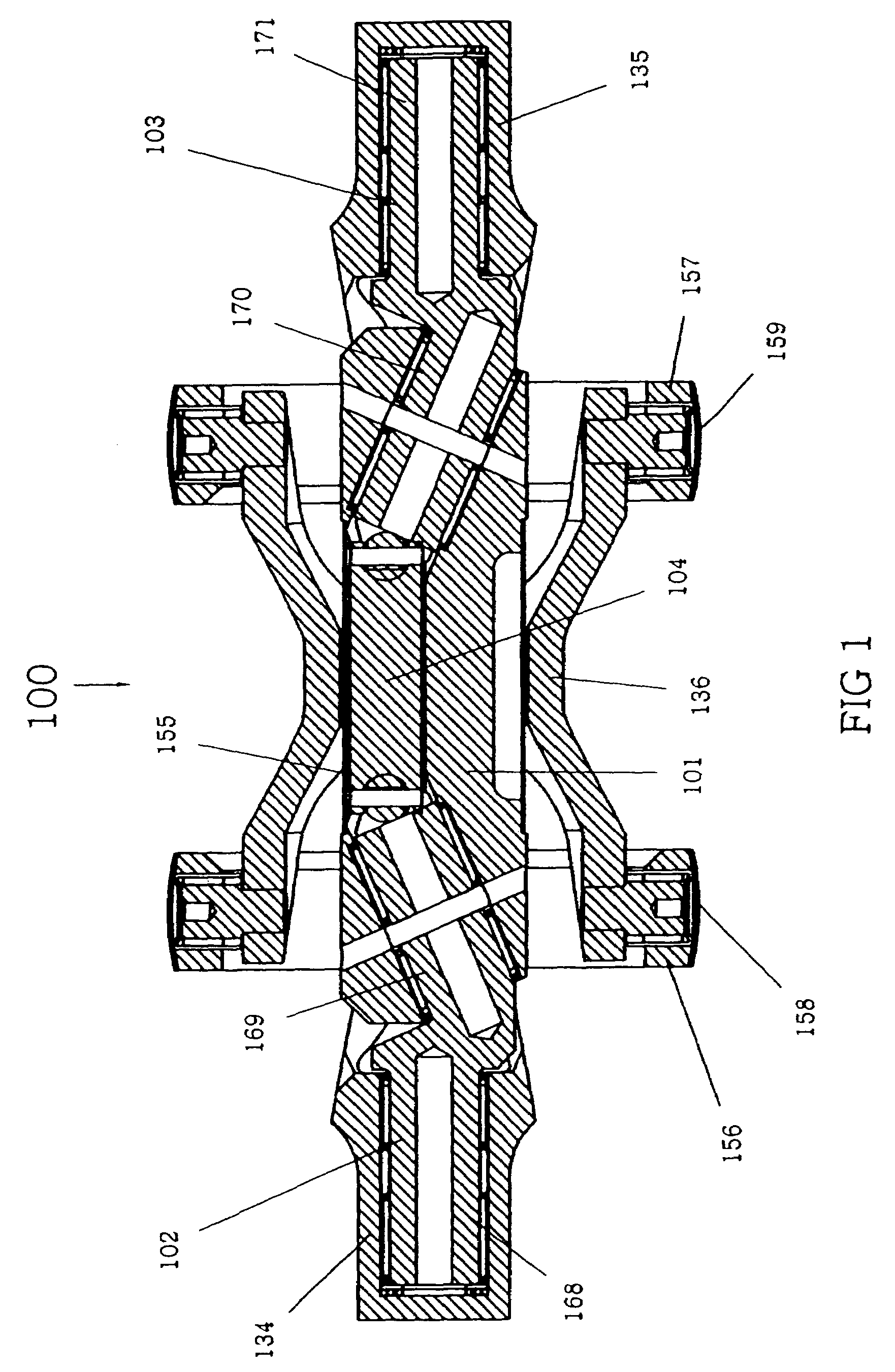
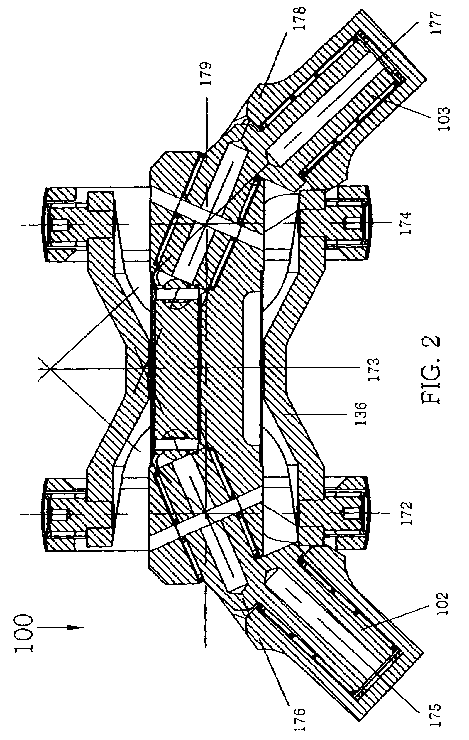
[0044]Universal joints 100, 200, 300, 400 and 500 include respective centering mechanisms 100A, 200B, 300C, 400D for supporting the universal joints and forcing the two joint halves to operate at the same angle thereby causing the joint to operate at constant velocity at all angles. For example, each shaft 134, 135 of the joint 100 is rotatably connected to the centering mechanism 100A. Movement of one of the shafts 134, 135 at an angle relative to the longitudinal axis of the connecting yoke 136 is transmitted to the other shaft 135, 134 by the centering mechanism 100A and the centering mechanism 100A causes the other shaft 135, 134 to likewise move at the same angle relative to the longitudinal axis of the connecting yoke 136. The centering mechanism 100A includes cam rods 102, 103 supported within a cam tube 101, which arrangement of bearings allows a full range of movement of the shafts 134, 135 at angles of 90°.

[0045]Universal joint 100 can be assembled by the following method:...


PUM


Abstract

Universal joint (100) includes a centering mechanism (100A) for supporting the universal and forcing the two joint halves to operate at the same angle thereby causing the joint to operate at constant velocity at all angles. Each shaft (134, 135) of the joint (100) is rotatably connected to the centering mechanism (100A). Movement of one of the shafts (134, 135) at an angle relative to the longitudinal axis of the coupling yoke (136) is transmitted to the other shaft (135, 134) by the centering mechanism (100A) and the centering mechanism (100A) causes the other shaft (135, 134) to likewise move at the same angle relative to the longitudinal axis of the coupling yoke (136). The centering mechanism (100A) includes cam rods (102, 103) supported within a cam tube (101), which arrangement allows a full range of movement of the shafts (134, 135) at angles of 90°.

Description

CROSS-REFERENCE TO RELATED APPLICATIONS[0001]This is a continuation of co-pending U.S. patent application Ser. No. 10 / 071,776, filed 7 Feb. 2002, now U.S. Pat. No. 6,773,353, which application claimed priority of U.S. Provisional Patent Application Ser. No. 60 / 267,017, filed 7 Feb. 2001, incorporated herein by reference.STATEMENT REGARDING FEDERALLY SPONSORED RESEARCH OR DEVELOPMENT[0002]Not applicableREFERENCE TO A “MICROFICHE APPENDIX”[0003]Not applicableBACKGROUND OF THE INVENTION[0004]1. Field of the Invention[0005]The present invention relates primarily to centering mechanisms. More particularly, the present invention relates primarily to centering mechanisms for universal joints.[0006]2. General Background of the Invention[0007]Universal joint designers have found it difficult to design constant velocity universal joints capable of operating at high angles, high speeds and high loads simultaneously, due to the limitations of existing constant velocity universal joint centering...

Claims


Application Information

Patent Timeline
Patent Type & Authority Patents(United States)
IPC IPC(8): F16D3/08F16D3/32F16D3/42
CPCF16D3/32Y10S464/905
Inventor CORNAY, PAUL J.CARSON, RICHARD J.NARVAEZ, PEDRO J.
Owner UNIVERSAL DRIVE TECH
Why Eureka
Try Eureka