
Magnified texture-mapped pixel performance in a single-pixel pipeline

a texture-mapped pixel and performance optimization technology, applied in the field of computer graphics, can solve the problems of increasing the complexity of images displayed, the complexity of images being sent to display devices, and the complexity of graphics processors with a great deal of processing power, and achieve the effect of improving the performance of magnified texture-mapped pixels

Inactive Publication Date: 2006-12-05
ORACLE INT CORP
View PDF11 Cites 10 Cited by
  • Summary
  • Abstract
  • Description
  • Claims
  • Application Information

AI Technical Summary

Benefits of technology

[0016]The problems set forth above may at least in part be solved in some embodiments by a system or method for improving magnified texture-mapped pixel performance in a single-pixel pipeline.

Problems solved by technology

Modern graphics systems, however, incorporate graphics processors with a great deal of processing power.
This change is due to the recent increase in both the complexity and amount of data being sent to the display device.
Similarly, the images displayed are now more complex and may involve advanced techniques such as anti-aliasing and texture mapping.
As a result, without considerable processing power in the graphics system, the CPU would spend a great deal of time performing graphics calculations.
This could rob the computer system of the processing power needed for performing other tasks associated with program execution and thereby dramatically reduce overall system performance.
Many implementations of graphics systems may have a limited amount of space available for implementing a graphics processor.

Method used


Image

  • Magnified texture-mapped pixel performance in a single-pixel pipeline
  • Magnified texture-mapped pixel performance in a single-pixel pipeline
  • Magnified texture-mapped pixel performance in a single-pixel pipeline

Examples


Embodiment Construction

Incorporation By Reference

[0041]U.S. patent application Ser. No. 10 / 094,934 titled “Improving Magnified Texture-Mapped Pixel Performance in a Single-Pixel Pipeline” and filed Mar. 11, 2002 (5181-88000) is hereby incorporated by reference in its entirety as though fully and completely set forth herein.

Computer System—FIG. 1

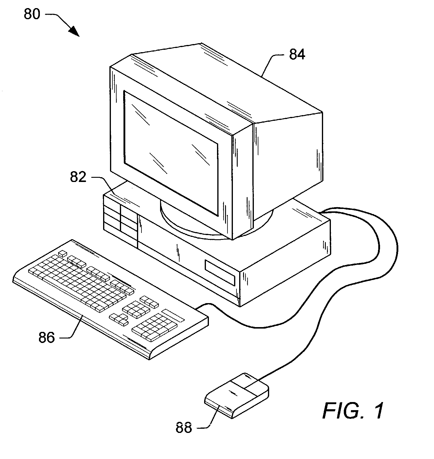
[0042]FIG. 1 illustrates one embodiment of a computer system 80 that includes a graphics system. The graphics system may be included in any of various systems such as computer systems, network PCs, Internet appliances, televisions (e.g. HDTV systems and interactive television systems), personal digital assistants (PDAs), virtual reality systems, and other devices which display 2D and / or 3D graphics, among others.

[0043]As shown, the computer system 80 includes a system unit 82 and a video monitor or display device 84 coupled to the system unit 82. The display device 84 may be any of various types of display monitors or devices (e.g., a CRT, LCD, or gas-plasma displa...


PUM


Abstract

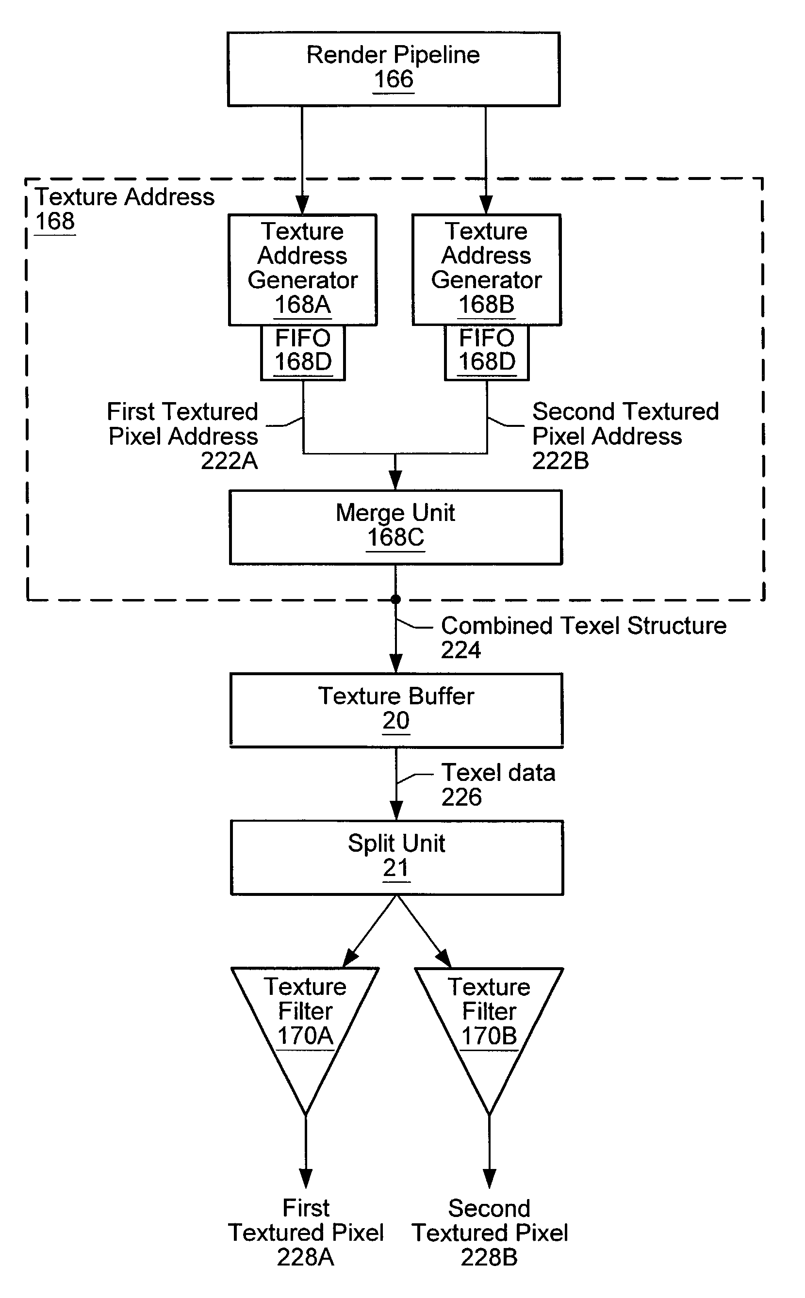
A system and a method for improving magnified texture-mapped pixel performance in a single-pixel pipeline. A plurality of textured pixel addresses corresponding to a plurality of pixels may be generated. A FIFO or other memory unit may be used to linearly order the plurality of textured pixel addresses. Two consecutive textured pixel addresses out of the plurality of textured pixel addresses may be examined if they map to a common set of texels in texture space. The two consecutive textured pixel addresses may be merged together and propagated down the pipeline if they map to the common set of texels. However, only a first of the two consecutive textured pixel addresses may be propagated down the pipeline if the two consecutive textured pixel addresses do not map to a common set of texels. Texel data may be generated in response to receiving either the combined texel structure or the first of the two textured pixel addresses. The texel data may be filtered using one or more texture filters in order to generate texture values. The next two textured pixel addresses that may be examined by the merge unit include the subsequent two consecutive textured pixel addresses, or a second of the two consecutive textured pixel addresses and a subsequent consecutive textured pixel address.

Description

CONTINUATION DATA[0001]This is a continuation-in-part of application Ser. No. 10 / 094,934 titled “Improving Magnified Texture-Mapped Pixel Performance in a Single-Pixel Pipeline” filed Mar. 11, 2002 now U.S. Pat. No. 6,847,372, whose inventors are Brian D. Emberling and Michael G. Lavelle, and which is assigned to Sun Microsystems Corporation.CROSS REFERENCE TO RELATED APPLICATIONS[0002]The following patents and / or patent applications are related to the present application.[0003]U.S. patent application Ser. No. 10 / 094,934 titled “Improving Magnified Texture-Mapped Pixel Performance in a Single-Pixel Pipeline” filed Mar. 11, 2002, whose inventors are Brian D. Emberling and Michael G. Lavelle, and which is assigned to Sun Microsystems Corporation.BACKGROUND OF THE INVENTION[0004]1. Field of the Invention[0005]This invention relates generally to the field of computer graphics and, more particularly, to performance optimization of graphics pipelines.[0006]2. Description of the Related Ar...

Claims


Application Information

Patent Timeline
IPC IPC(8): G09G5/00G06T7/40G06T15/00G06T15/04
CPCG06T15/005G06T15/04
Inventor EMBERLING, BRIAN D.LAVELLE, MICHAEL G.
Owner ORACLE INT CORP
Learn More