Ultra wideband transmitter

a transmitter and wideband technology, applied in the field of ultra wideband communication, can solve the problems of increasing traffic across the internet, requiring significant bandwidth for transmission of large data files, and only increasing at a faster rate, so as to increase the available increase the bandwidth of a communication system, or the effect of increasing the data ra

Inactive Publication Date: 2006-12-05
INTELLECTUAL VENTURES HOLDING 81 LLC
View PDF29 Cites 4 Cited by
  • Summary
  • Abstract
  • Description
  • Claims
  • Application Information

AI Technical Summary

Benefits of technology

[0008]One embodiment of the present invention provides a transmitter system that increases the available bandwidth of a communication system by enabling the simultaneous transmission of conventional carrier-wave signals and ultra-wideband pulses. The transmitter system of the present invention enables the simultaneous coexistence of the ultra-wideband pulses with conventional carrier-wave signals. The present invention may be used in wireless and wire communication networks such as hybrid fiber-coax networks.
[0009]In one embodiment of the present invention, the transmitter system includes a data modulation unit, a transmitter unit, and an antenna. One feature of the present invention is that the transmitted ultra-wideband pulses have a spectral power density that does not cause interference with other communication signals. Thus, the ultra-wideband pulses transmitted according with the present invention enable a significant increase in the bandwidth, or data rates of a communication system.

Problems solved by technology

Moreover, traffic across the Internet continues to increase, and with the introduction of new applications, such as the convergence of voice and Internet data, traffic will only increase at a faster rate.
Such transmissions require significant bandwidth to transmit the large data files in a reasonable amount of time.
The need for more bandwidth is evidenced by user complaints of slow Internet access and dropped data links that are symptomatic of network overload.

Method used


Image

  • Ultra wideband transmitter
  • Ultra wideband transmitter
  • Ultra wideband transmitter

Examples


Embodiment Construction

[0032]In the following paragraphs, the present invention will be described in detail by way of example with reference to the attached drawings. Throughout this description, the preferred embodiment and examples shown should be considered as exemplars, rather than as limitations on the present invention. As used herein, the “present invention” refers to any one of the embodiments of the invention described herein, and any equivalents. Furthermore, reference to various feature(s) of the present invention throughout this document does not mean that all claimed embodiments or methods must include the referenced feature(s).

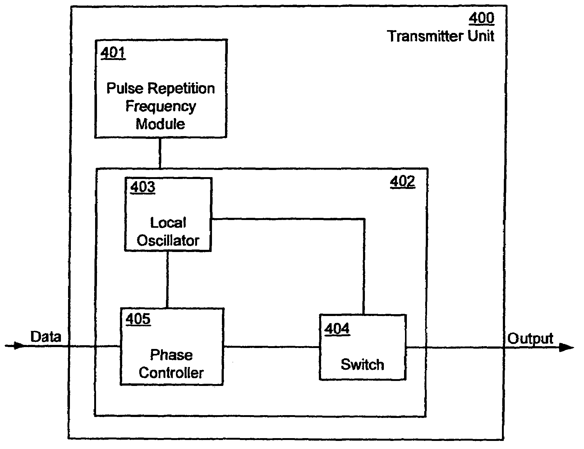
[0033]The present invention provides a method of transmitting an ultra-wideband signal. In a preferred embodiment, the present invention comprises an ultra-wideband transmitter that phase shifts a continuous cyclic signal to a specific center frequency.

[0034]The pulse can be transmitted and received wirelessly, or through any wire medium, whether the medium is twisted-...


PUM


Abstract

An ultra-wideband transmitter is provided. In one embodiment, the transmitter uses a monopulse of a continuous cyclic signal to phase shift a data pulse. The data pulses and the cyclic signal may be modulated by varying a phase of the data pulses and cyclic signal. The phase shifted data pulse may be used to generate an ultra-wideband pulse for transmission. The modulated data pulses and cyclic signal may be gated such that the data pulse and only a monopulse of the cyclic signal pass through the logic gate. This Abstract is provided for the sole purpose of complying with the Abstract requirement rules that allow a reader to quickly ascertain the subject matter of the disclosure contained herein. This Abstract is submitted with the explicit understanding that it will not be used to interpret or to limit the scope or the meaning of the claims.

Description

FIELD OF THE INVENTION[0001]The present invention relates to ultra-wideband communications. More particularly, the invention concerns an ultra-wideband transmitter.BACKGROUND OF THE INVENTION[0002]The Information Age is upon us. Access to vast quantities of information through a variety of different communication systems are changing the way people work, entertain themselves, and communicate with each other. For example, as a result of increased telecommunications competition mapped out by Congress in the 1996 Telecommunications Reform Act, traditional cable television program providers have evolved into full-service providers of advanced video, voice and data services for homes and businesses. A number of competing cable companies now offer cable systems that deliver all of the just-described services via a single broadband network.[0003]These services have increased the need for bandwidth, which is the amount of data transmitted or received per unit time. More bandwidth has become...

Claims


Application Information

Patent Timeline
Patent Type & Authority Patents(United States)
IPC IPC(8): H04L27/04H04BH04B1/69
CPCH04B1/7174H04B1/7172
Inventor CARBONARI, DAVID
Owner INTELLECTUAL VENTURES HOLDING 81 LLC
Why Eureka
Try Eureka