System for transfer of a fluid product, particularly liquefied natural gas, between a transport vehicle, such as a ship, and an installation for receiving or supplying this product
a technology for transferring systems and fluid products, which is applied in the direction of container discharge methods, special purpose vessels, packaging goods, etc., can solve the problems that the transfer systems for liquefied natural gas are not suitable for use, and achieve the effect of reducing or cancelling stresses
- Summary
- Abstract
- Description
- Claims
- Application Information
AI Technical Summary
Benefits of technology
Problems solved by technology
Method used
Image
Examples
first embodiment
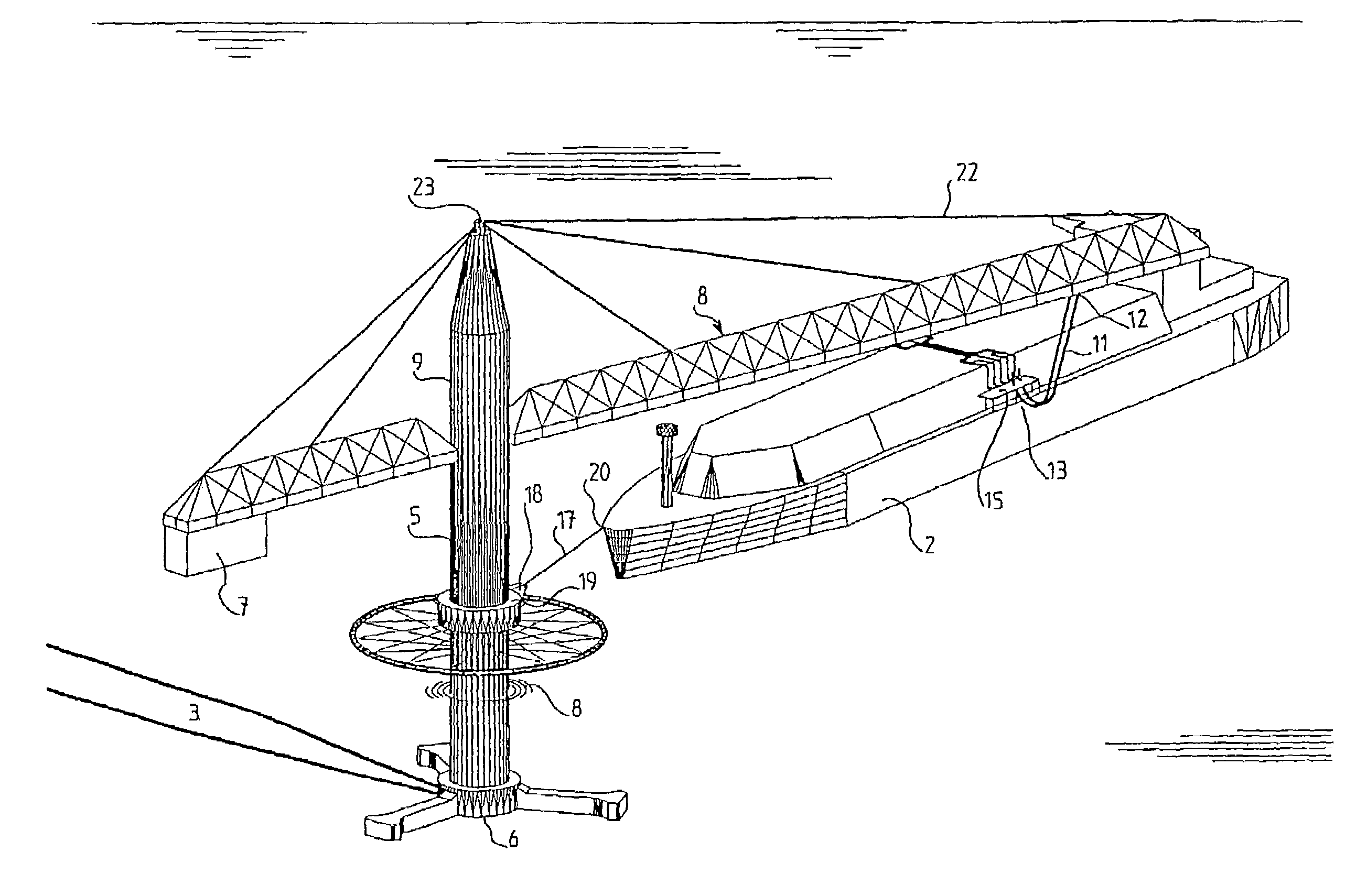
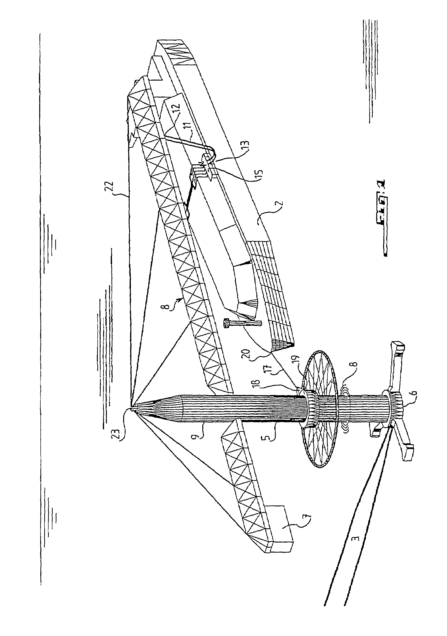
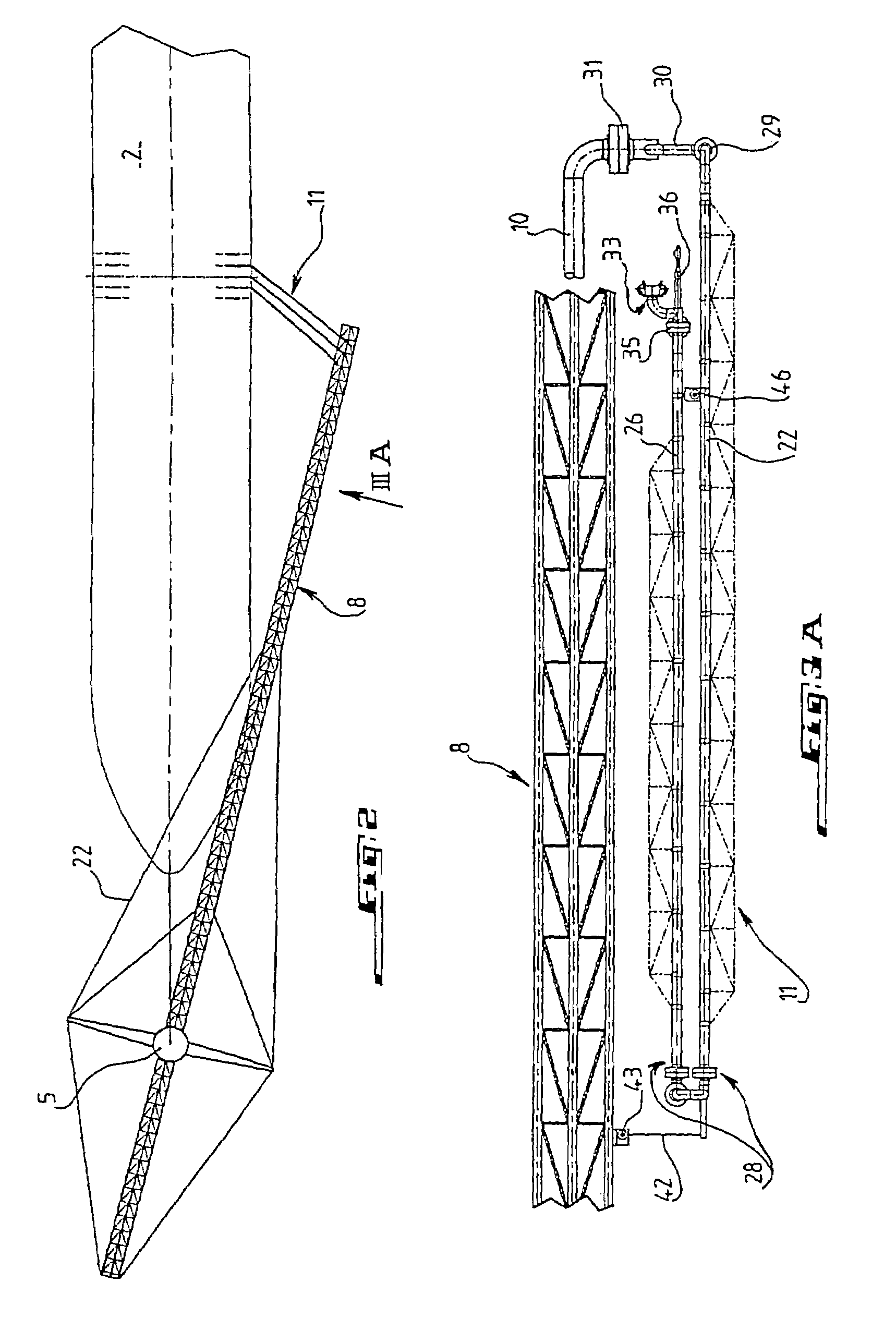
[0050]fluid transfer device 11 according to the invention will now be described with reference to FIGS. 3A to 3I. According to this embodiment, the device has three pairs of articulated arms, which are connected in parallel to fixed pipe 10 supported by boom 8, each pair having inner arm 25 and outer arm 26. The two arms are connected to one another by articulation 28 of the type with two rotating joints with perpendicular axes, thus forming a universal joint. The upper end of each inner arm 25 is connected by rotating joint 29 to a limb of E-shaped part 30, whose base is connected by rotating joint 31 to fixed pipe 10. The axes of rotation of the two joints 29 and 31 are perpendicular. The free end of each outer arm 26 carries connector 33 allowing connection of the arm to manifold 15 of the ship. The connector is joined to the arm by means of two rotating joints 35 with perpendicular axes. Rigidly associated with the connector is centering rod 36, popularly called a “spindle,” whi...
second embodiment
[0055]the fluid transfer system according to the invention will be described hereafter with reference to FIGS. 4A to 4P. This embodiment has the particularity, with respect to the embodiment just described, that the deformable transfer device has cryogenic hoses bearing the reference 50. As seen in FIGS. 4A to 4E, the device represented as an example has three hoses 50, mounted in parallel, that are connected to an end of an E-shaped part 30 and are connected to fixed pipe 10 by the intermediary of two rotating joints 31 with perpendicular axes. The cryogenic hoses could be hoses such as those as developed, for example, by the company Coflexip Stena Offshore. The other end of each cryogenic hose carries connector 33, which is provided with a centering rod called a “spindle”36, and which is intended for mounting on manifold device 15 of the ship, if applicable, via the intermediary of connecting module 38.
[0056]Each connector 33 is suspended by a cable 56 which can be wound on winch ...
PUM
| Property | Measurement | Unit |
|---|---|---|
| Length | aaaaa | aaaaa |
| Length | aaaaa | aaaaa |
| Length | aaaaa | aaaaa |
Abstract
Description
Claims
Application Information
 - R&D
- Intellectual Property
- Life Sciences
- Materials
- Tech Scout
- Unparalleled Data Quality
- Higher Quality Content
- 60% Fewer Hallucinations
Browse by: Latest US Patents, China's latest patents, Technical Efficacy Thesaurus, Application Domain, Technology Topic, Popular Technical Reports.
© 2025 PatSnap. All rights reserved.Legal|Privacy policy|Modern Slavery Act Transparency Statement|Sitemap|About US| Contact US: help@patsnap.com


