
Device to prevent the formation of solid matter due to projections on an air outlet

Inactive Publication Date: 2006-12-12
NEXTER SYST SA
View PDF10 Cites 17 Cited by
  • Summary
  • Abstract
  • Description
  • Claims
  • Application Information

AI Technical Summary

Benefits of technology

[0018]Another advantage of the invention lies in the fact that the projections cast on the fins are cast off before they build up.
[0019]Yet another advantage of the device according to the invention lies in that it allows air or gas outlets to be provided on an armored vehicle without compromising its infrared invisibility. In fact, the hot air outlets may in this case be placed under the vehicle in a suitable place thus making it difficult or even impossible for the heat source to be detected.
[0020]Yet another advantage of the invention lies in its simple design and in the ease with which a fin may be replaced in case of fracture.

Problems solved by technology

After a while, these vents are completely blocked thus considerably hindering the air outlet process.
They therefore have to be cleaned by hand, which is often difficult if not impossible.
Moreover, if this built-up material dries, cleaning by hand becomes extremely difficult.

Method used


Image

  • Device to prevent the formation of solid matter due to projections on an air outlet
  • Device to prevent the formation of solid matter due to projections on an air outlet

Examples


Embodiment Construction

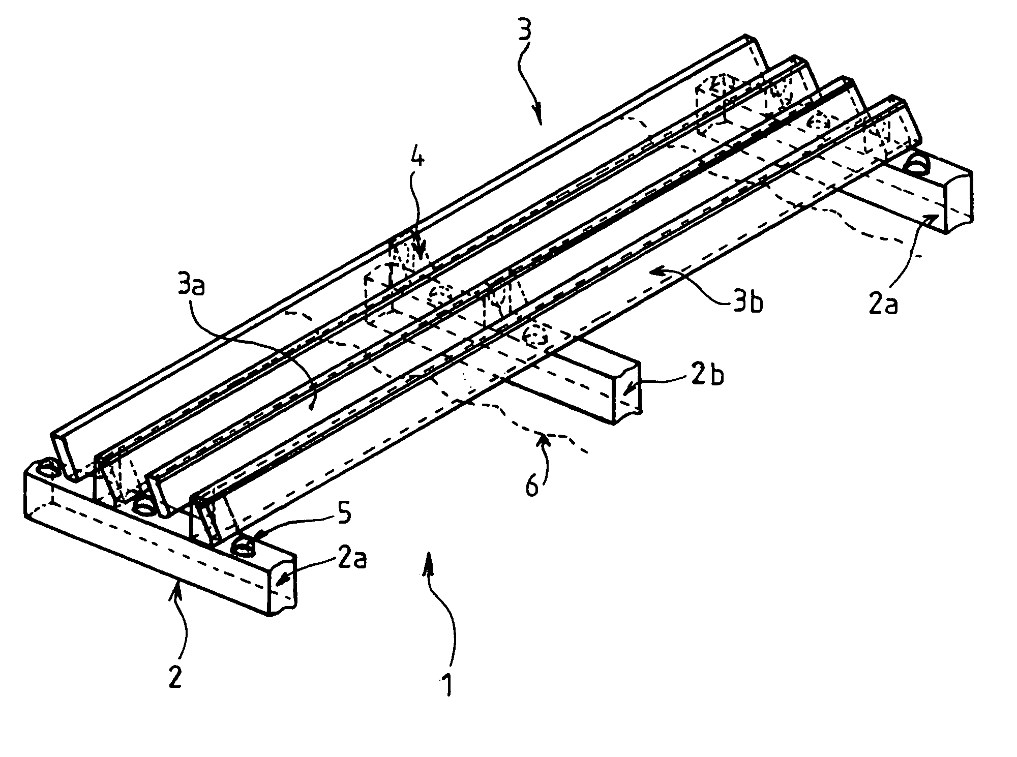
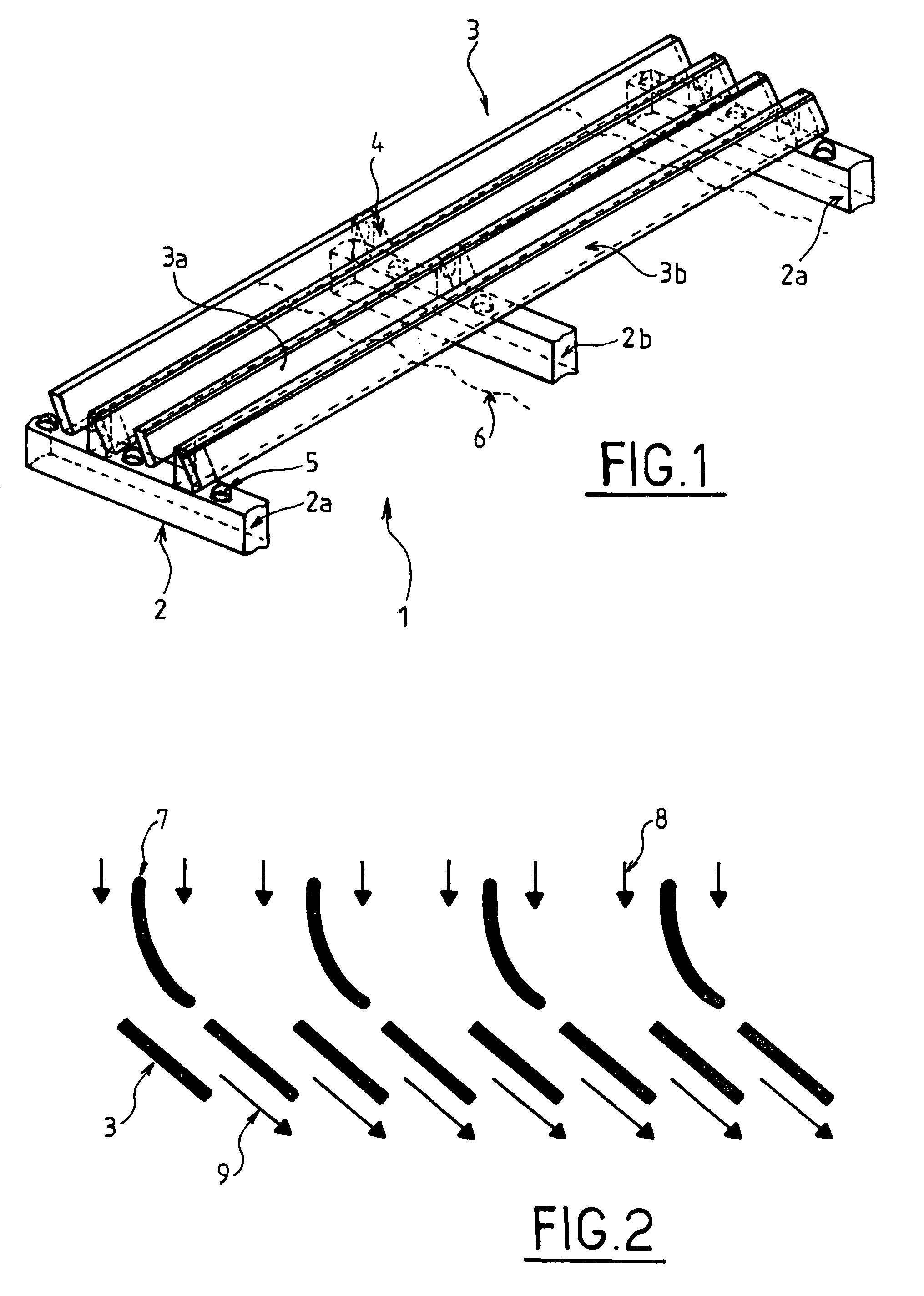
[0024]FIG. 1 shows a shutter 1 constituted by a support 2 and fins 3. The shutter is fixed to the mouth of an air duct not shown, further details of which are not necessary. The fins are in the form of an elongated plate, for example rectangular, placed obliquely with respect to the support.

[0025]Since the fins must vibrate, they cannot have a curve perpendicular to their axis and must be in a plane.

[0026]The drawing shows three bars 2 to fasten the vibrating fins, two end bars 2a and one central 2b bar. Intermediate fastening parts 4 for the fins 3 are shown on the bars 2. These intermediate fastening parts must ensure flexible fastening allowing the fins to vibrate, as well as an inclined position for the fins with respect to the plane of the air outlet. The fins may be fastened to these parts by welding, screwing, bolting or any other known process (multi-riveting, latching, pinching, pinning, etc.).

[0027]In the example shown, the shutter is fitted with two types of vibrating fin...


PUM

PropertyMeasurementUnit
Thicknessaaaaaaaaaa
Metallic bondaaaaaaaaaa
Frequencyaaaaaaaaaa

Abstract

The invention relates to a device to prevent the formation of solid matter due to projections on an air outlet, for example that of an armored vehicle, located near to such projections.It comprises a shutter 1 incorporating at least two vibrating fins 3 fixed onto a support 2, said fins being of two different types mounted alternatively and vibrating differently. One vibrating fin 3a is connected to the support by a number N of fastenings and the other vibrating fin 3b by a number N+ / −1 fastenings. The support 2 for the vibrating fins is constituted by an assembly of bars 2a, 2b that are substantially perpendicular to the fins 3. Abutments 5 are placed on the fins 3 or on the support 2.

Description

BACKGROUND OF THE INVENTION[0001]1. Field of the Invention[0002]The technical scope of the invention is that of devices allowing flow outlets to be protected from the formation of a solid matter due to projections that may be cast onto them.[0003]2. Description of the Related Art[0004]Air outlets, in particular on a vehicle, are more often than not of a simple form, that is to say fitted with vents. These air outlets are generally near to materials of all types that are projected onto the vents and build up. After a while, these vents are completely blocked thus considerably hindering the air outlet process. They therefore have to be cleaned by hand, which is often difficult if not impossible. Moreover, if this built-up material dries, cleaning by hand becomes extremely difficult.SUMMARY OF THE INVENTION[0005]The aim of the invention is thus to overcome such drawbacks by allowing the air outlets to be positioned, on vehicle for example, in places exposed to projections, whilst avoid...

Claims


Application Information

Patent Timeline
IPC IPC(8): B60K13/04B60H1/00B60H1/26B60K11/08
CPCB60H1/00357B60H1/26B60K13/04B60K11/08
Inventor BRUN, MICHELCARLIER, SYLVAINSAUNIER, ANTOINE
Owner NEXTER SYST SA
Learn More