Artificial synapse chip

a technology of artificial synapse and chip, which is applied in the direction of artificial respiration, prosthesis, therapy, etc., can solve the problems of permanent damage to the photoreceptor, visual impairment or blindness, and ineffective treatment for most patients

Inactive Publication Date: 2006-12-12
THE BOARD OF TRUSTEES OF THE LELAND STANFORD JUNIOR UNIV
View PDF11 Cites 62 Cited by
  • Summary
  • Abstract
  • Description
  • Claims
  • Application Information

AI Technical Summary

Benefits of technology

[0017]FIG. 1B is a plan view of the artificial synapse chip of FIG. 1A;
[0018]FIG. 1C is a cross-sectional view of the artificial synapse chip of FIG. 1A taken along plane 1C—1C;

Problems solved by technology

Disturbances at any step in the process may lead to visual impairment or blindness.
Currently, there is no effective treatment for most patients with AMD, a disease that often results in permanent damage to photoreceptors, but spares most retinal ganglion cells (RGCs) and second-order neurons, such as bipolar and horizontal cells.
Although these trials have demonstrated that vision is recoverable in a limited fashion, major challenges remain.
Due to the size and difficulties in placement of most available electrodes, imprecise electric field stimulation extending over long distances (several cell-body diameters) is used to depolarize neurons.
However, such methods often require excessive stimulation, which may be harmful, leading to inflammation of the stimulated region and even to excessive growth of glial cells or gliosis.
The limitations in using electrical stimulation warrant the need for other methodologies that do not use electrical stimulation.

Method used


Image

  • Artificial synapse chip
  • Artificial synapse chip
  • Artificial synapse chip

Examples


example 1

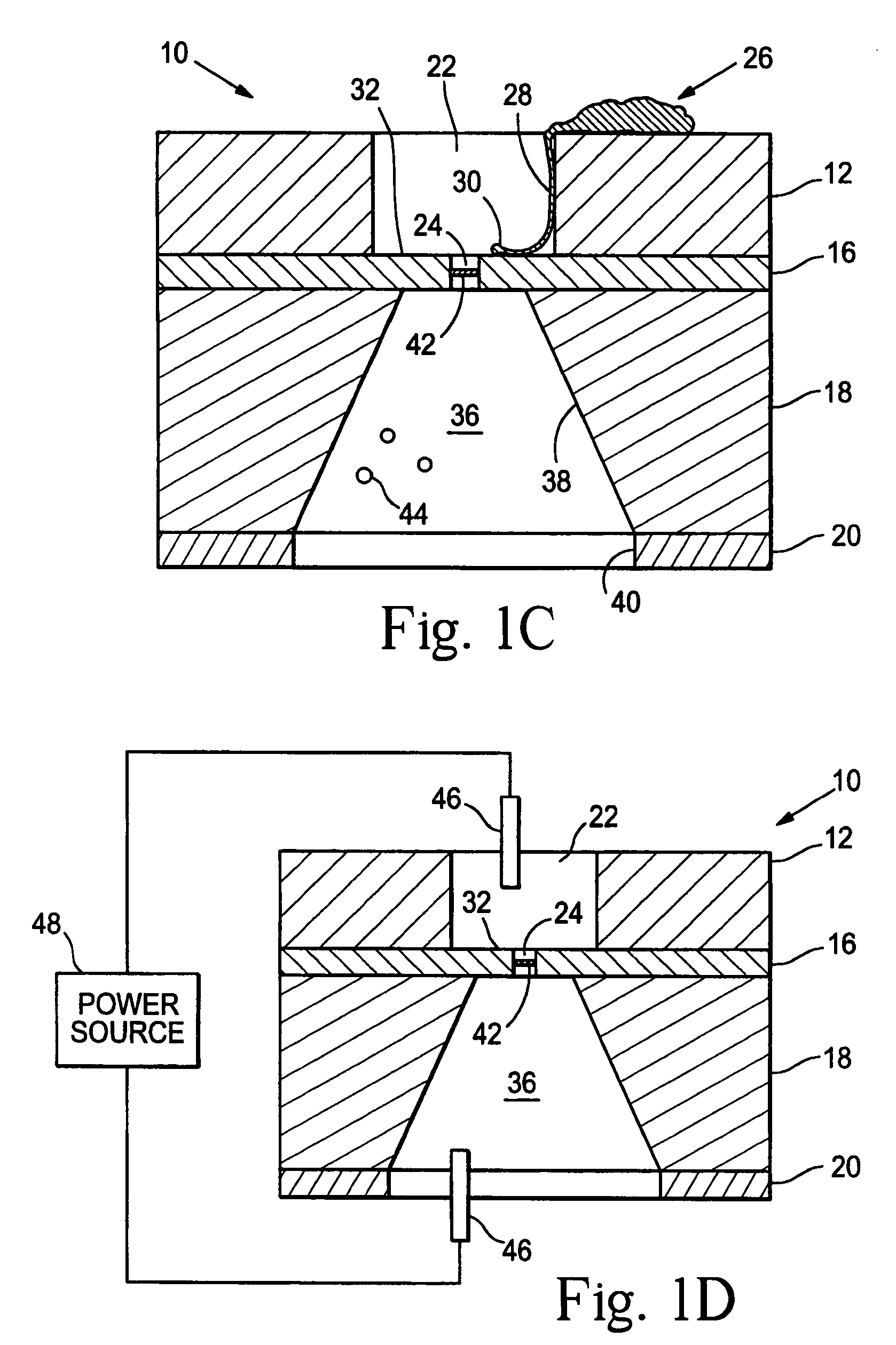
[0108]Methods for stimulating cells through the nanoaperture and measuring their activity using fluorescence from Ca2+ sensitive dyes include the following: (1) voltage clamping of the cell to the aperture (applying suction via the microchannel) and varying the voltage of the buffer in the microfluidic channel; (2) chemical stimulation of the cell by pulsing a bolus of neurotransmitter to the under side of the cell; (3) microfluidic bolus of liposomes containing neurotransmitters to the aperture opening; and (4) microfluidic reservoir of engineered cells that would stimulate the neurite through the release of the transmitters.

[0109]A subconfluent layer of PC12 cells is cultured on an array of microapertures. Cell activity is measured by fluorescence microscopy with the cells loaded with a Ca+2 sensitive dye (e.g. indo-1, fura-2, fluo-3, calcium green, aequorin). The fluorescence serves both to monitor the activity of the cell directly above the aperture and to see the effect on neig...

example 2

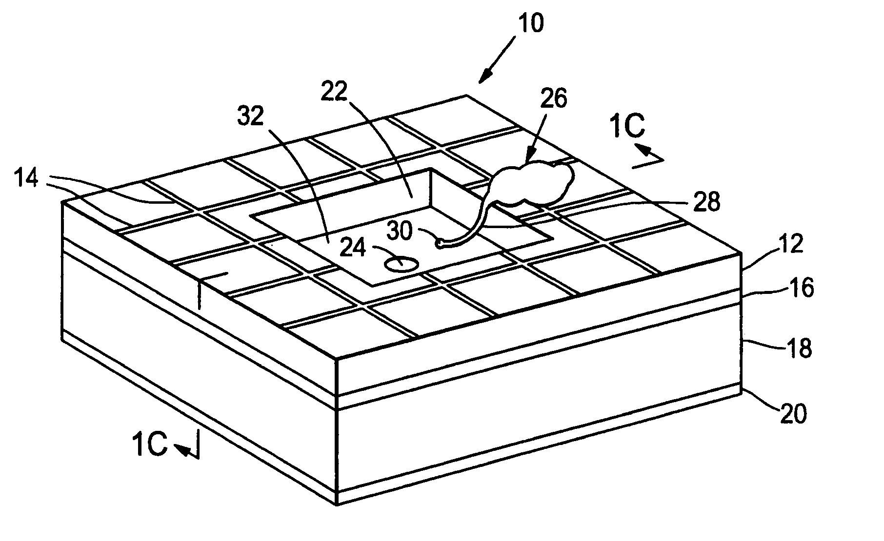
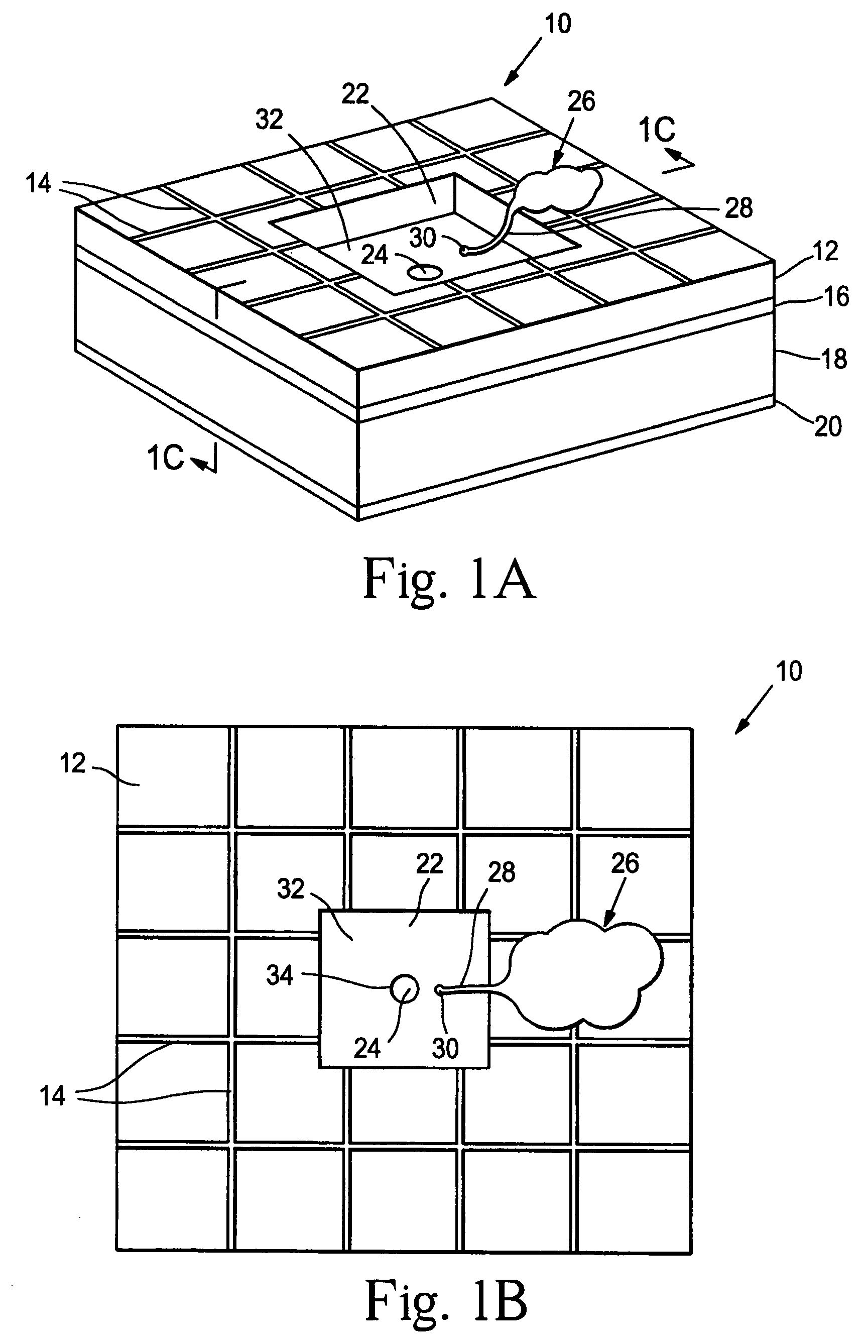
[0112]A prototype neural interface device was developed that is described in Peterman, et al., supra. The basic component in the 8′8 mm device is a small circular aperture in the side of a microfluidic channel. Using standard microfabrication techniques, a thin layer of silicon nitride (1.6μ thick) was deposited on a silicon wafer. Four circular apertures were etched through the silicon nitride in a 2′2 array (5μ diameter, 125μ center-to-center). The silicon wafer was then anisotropically etched through the silicon wafer, creating a thin, free standing membrane roughly 350μ on a side. Channels were created by lithographically patterning 25μ deep SU-8 photoresist over the apertures. The 50μ wide channels were designed with a bend to allow each channel to overlay a single aperture. The bend provides sufficient room for inlet and outlet connections to each channel. Gold electrodes for controlling electroosmotic flow are patterned inside the channels with two common grounds and four con...

example 3

[0122]In another study, the prosthesis device material consisted of a combination of SU-8 photoresist (MicroChem Corp.) and PDMS. The device was prepared substantially as described in FIG. 2. To alleviate adhesion between the PDMS layers and the silicon substrate, a thin gold layer (100 nm) was deposited on a blank four-inch silicon wafer. A layer of SU-8 was spun on the gold at ˜40μ thick as per the manufacturer's specifications. The SU-8 was exposed to define the negative of the channels. After development, PDMS was spun on the wafer at a thickness greater than the SU-8 structures. The PDMS at this point was quite flexible and self-adhesive. The PDMS was first treated in an oxygen plasma (155 W, 60 sec) and a thin layer of SU-8 was spun onto the substrate. The SU-8 layer adhered to the PDMS, stiffened the material and limited the self-adhesion. After the SU-8 was gross exposed and hard baked, the PDMS-SU-8 bilayer was peeled from the silicon wafer as a sheet.

[0123]On a second wafe...


PUM

PropertyMeasurementUnit
thicknessaaaaaaaaaa
thicknessaaaaaaaaaa
volumeaaaaaaaaaa

Abstract

Devices and methods are provided for administering a fluid to a neuronal site. The device comprises a reservoir, an aperture in fluid connection to the reservoir, and electrical means for moving to the fluid to or through the aperture. The electrical means may take the form of electroosmotic force, piezoelectric movement of a diaphragm or electrolysis of a solution. The electrical means may be external to the host, implanted in the host or may be photodiodes activated by light, particularly where the neuronal site is associated with the retina.

Description

CROSS-REFERENCE TO RELATED APPLICATIONS[0001]This application is a continuation-in-part of Ser. No. 10 / 184,210, filed Jun. 27, 2002 now U.S. Pat. No. 7,001,608, which claimed priority of provisional application Ser. No. 60 / 301,934, filed Jun. 29, 2001, and provisional application Ser. No. 60 / 450,980, filed Feb. 27, 2003, which are incorporated herein in their entirety as if set forth herein.BACKGROUND OF THE INVENTION[0002]1. Field of the Invention[0003]The field of this invention is microfabricated medical devices.[0004]2. Background Information[0005]Light entering the eye through the cornea is focused through the lens (which further focuses the light) onto the retina, a thin layer of cells in the back of the eye. Normal human vision depends upon signals generated by neurons in the retina. The visual signals originate with the photoreceptor cells in the retina, which sense and respond to light, generating signals that in turn create and shape nerve signals in retinal ganglion cells...

Claims


Application Information

Patent Timeline
Patent Type & Authority Patents(United States)
IPC IPC(8): A61F2/14A61K9/22A61L27/00A61N1/05A61N1/30A61N1/36C12M1/42C12M3/00C12N5/0793G06N3/06
CPCA61N1/0543A61N1/30A61N1/326A61N1/36046C12N5/0619G06N3/061C12N2503/00C12N2535/10
Inventor FISHMAN, HARVEY A.BLOOM, DAVIDBENT, STACEY F.PETERMAN, MARK C.NOOLANDI, JAANMEHENTI, NEVILLE
Owner THE BOARD OF TRUSTEES OF THE LELAND STANFORD JUNIOR UNIV
Why Eureka
Try Eureka