Electric potential sensor

a technology of electric potential and output signal, which is applied in the direction of electrostatic field measurement, instruments, electrographic process apparatus, etc., can solve the problems of driving noise, affecting the accuracy of sensing, driving noise, etc., and achieve the effect of preventing or reducing the unfavorable mixing of driving noise and output signal of the detecting electrod

Inactive Publication Date: 2006-12-12
CANON KK
View PDF10 Cites 35 Cited by
  • Summary
  • Abstract
  • Description
  • Claims
  • Application Information

AI Technical Summary

Benefits of technology

[0010]In an electric potential sensor of the present invention, entrance of lines of electric force (electric fields) due to the electrostatic force of the capacity modulating unit into the detecting electrode can be prevented or reduced, so that unfavorable mixing of driving noise into an output signal of the detecting electrode can be prevented or reduced.

Problems solved by technology

The driving noise results from fields that are generated by a driver for driving the shutter and that reach the detecting electrode.
In such a case, driving noise due to those electric fields is likely to mix with an output signal from the detecting electrode.
The driving noise disadvantageously affects an accurate sensing, and reduces the sensitivity of a potential sensor.

Method used


Image

  • Electric potential sensor
  • Electric potential sensor
  • Electric potential sensor

Examples


first embodiment

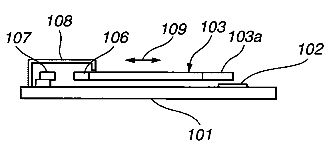
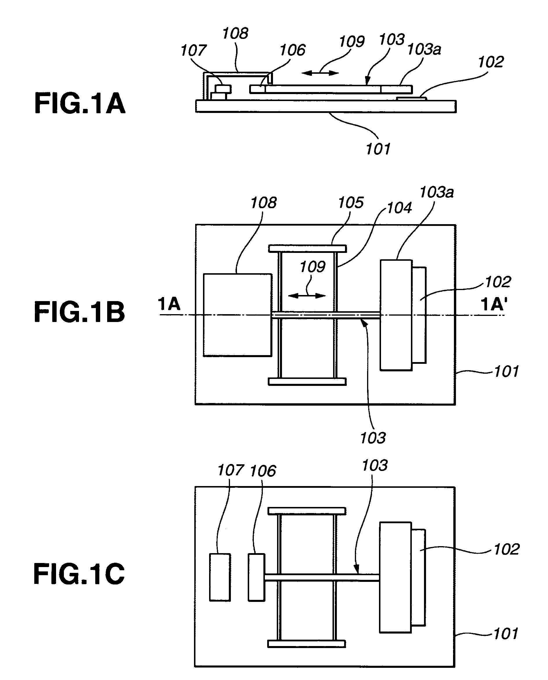
[0032]A first embodiment directed to an electric potential sensor will be described with reference to FIGS. 1A to 1C. As illustrated in FIGS. 1A to 1C, the electric potential sensor of this embodiment includes a substrate 101, a detecting electrode 102 formed on the substrate 101, a shutter member 103, elastic beams 104, a pair of anchor members 105, a stationary electrode 107, and an electric shield 108. The shutter member 103 includes a movable electrode 106 formed at its one end and a shutter portion 103a formed at its other end. The shutter member 103 moves in such a reciprocal manner that the shutter portion 103a can variably cover the detecting electrode 102 to periodically change the electric field that reaches the detecting electrode 102 from a measurement object (not shown).

[0033]Each elastic beam 104 is connected to an intermediate portion of the shutter member 103 to permit the reciprocating motion of the shutter member 103. Each anchor member 105 is connected to outermos...

sixth embodiment

[0066]In the structure of the above-discussed sixth embodiment, upon swinging rotation of the swingingly-rotatable member 1101, distances between the two detecting electrodes 1102 and a measurement object (not shown) change in a mutually-opposite phase. Accordingly, coupling capacitances between the two detecting electrodes 1102 and the measurement object periodically change in a mutually-opposite phase. An electric potential of the measurement object can be measured by processing output signals from the two detecting electrodes 1102 in a differential manner in the signal processing circuit. The number of detecting electrodes is not necessarily limited to two. Function of a potential sensor can be likewise achieved when only one detecting electrode is used.

[0067]In the structure of FIG. 9A, however, lines of electric force from an electrostatic force generation portion 1300 reach a region 1200 of the detecting electrode 1102, generating driving noise. In the sixth embodiment, theref...

seventh embodiment

[0069]Description will now be given for an image forming apparatus of a seventh embodiment using an electric potential sensor of the present invention, with reference to FIG. 10. In FIG. 10, reference numeral 801 designates an electric potential sensor of the present invention. Reference numeral 802 designates an electrostatic charging device. Reference numeral 803 designates a signal processing device. Reference numeral 804 designates a high-voltage generating device. Reference numeral 805 designates a light exposing device. Reference numeral 806 designates a toner supplying device. Reference numeral 807 designates a transferring material conveying roller. Reference numeral 808 designates a photosensitive drum. Reference numeral 809 designates a transferring material sandwiched between the transferring material conveying roller 807 and the photosensitive drum 808.

[0070]An electric potential distribution on the photosensitive drum 808 can be measured when an output of the potential ...


PUM


Abstract

An electric potential sensor includes a detecting electrode, a capacitor modulating unit for modulating a coupling capacitance between the detecting electrode and a measurement object by using an electrostatic force, and a shielding unit for electrically shielding the detecting electrode from electric fields due to the electrostatic force of the capacitor modulating unit. An electric potential of the measurement object is measured based on a change caused by the capacitor modulating unit in the amount of electrical charge induced in the detecting electrode. Entrance of lines of electric force due to the electrostatic force of the capacity modulating unit into the detecting electrode is prevented or reduced, so that an unfavorable mixture of driving noise into an output signal of the detecting electrode can be prevented or reduced.

Description

BACKGROUND OF THE INVENTION[0001]1. Field of the Invention[0002]The present invention relates to a non-contacting electric potential sensor capable of measuring an electric potential of an object to be measured (a measurement object) based on the amount of electrical charge induced in a detecting electrode, and apparatuses, such as an image forming apparatus, using the electric potential sensor.[0003]2. Description of the Related Background Art[0004]Conventionally, there exists technology according to which a shutter disposed between a measurement object and a detecting electrode is driven to change the amount of electrical charge induced in the detecting electrode, and a surface electric potential of the measurement object is measured based on a change in the amount of electrical charge (see Solid-State Sensors and Actuators (The 7th International Conference) pp. 878–881). In such technology, the shutter is driven in a vacuum to achieve a low-voltage drive of the shutter, and drivi...

Claims


Application Information

Patent Timeline
Patent Type & Authority Patents(United States)
IPC IPC(8): G03G15/00G01R29/12
CPCG03G15/5037
Inventor USHIJIMA, TAKASHIICHIMURA, YOSHIKATSUKANDORI, ATSUSHIZAITSU, YOSHITAKA
Owner CANON KK
Why Eureka
Try Eureka