
Stereoscopic image display

a stereoscopic image and display technology, applied in the field of stereoscopic image display, can solve the problems of poor vertical viewing angle, reduce the luminance of 2d and 3d images, reduce the aperture ratio, etc., and achieve the effect of preventing or reducing noise and reducing the degradation of driving characteristics

Active Publication Date: 2016-02-09
LG DISPLAY CO LTD
View PDF6 Cites 0 Cited by
  • Summary
  • Abstract
  • Description
  • Claims
  • Application Information

AI Technical Summary

Benefits of technology

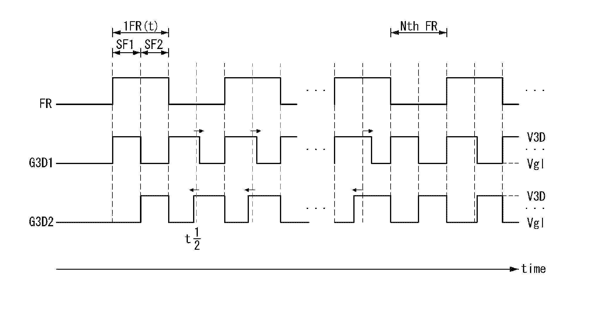
[0011]The embodiments disclosed herein provide a stereoscopic image display capable of reducing degradation of driving characteristics of thin film transistors included in switchable black stripes and preventing or reducing a noise generated when a gate voltage of the thin film transistors changes.

Problems solved by technology

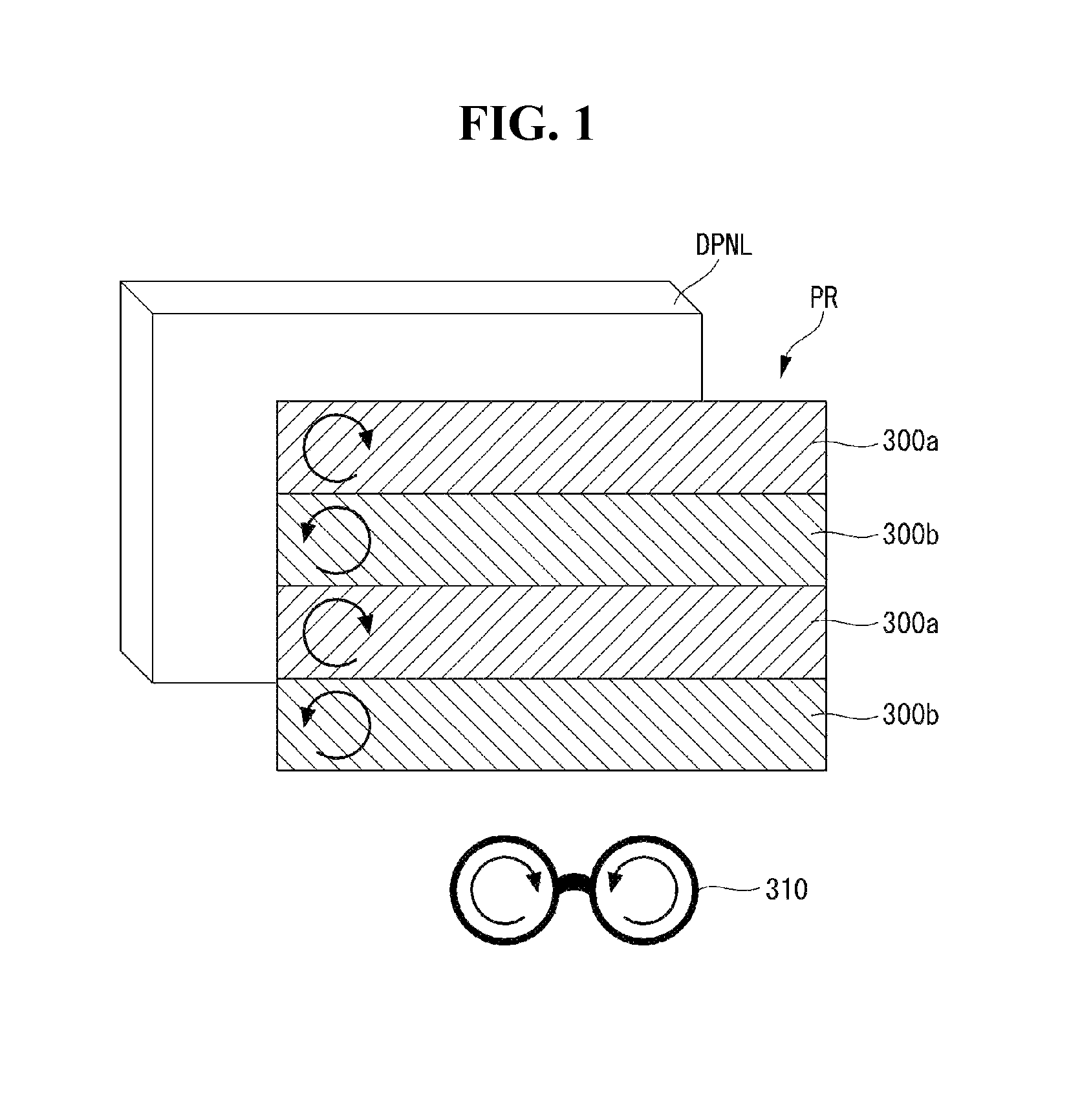
A parallax is generated between a pixel array of the liquid crystal display panel and the patterned retarder due to a thickness of an upper glass substrate of the liquid crystal display panel and a thickness of an upper polarizing plate, and thus leads to a poor vertical viewing angle.
Further, an increase in the width of the black matrices may reduce an aperture ratio, thereby reducing the luminance of the 2D and 3D images.
In this instance, the TFT of the switchable black stripe may undergo degradation of driving characteristics, including a shift of a threshold voltage, because of its gate bias stress.
As a result, when the luminance of the pixels changes due to the changes in the 3D control voltage, a noise may appear in the display panel.

Method used


Image

  • Stereoscopic image display
  • Stereoscopic image display
  • Stereoscopic image display

Examples


Embodiment Construction

[0030]The invention will be described more fully hereinafter with reference to the accompanying drawings, in which example embodiments of the inventions are shown. This invention may, however, be embodied in many different forms and should not be construed as limited to the embodiments set forth herein. Like reference numerals designate like elements throughout the specification. In the following description, if it is decided that the detailed description of known function or configuration related to the invention makes the subject matter of the invention unclear, the detailed description is omitted.

[0031]A stereoscopic image display according to one embodiment may be implemented based on a liquid crystal display. The liquid crystal display may be implemented as any type liquid crystal display including a transmissive liquid crystal display, a transflective liquid crystal display, and a reflective liquid crystal display. The transmissive liquid crystal display and the transflective ...


PUM


Abstract

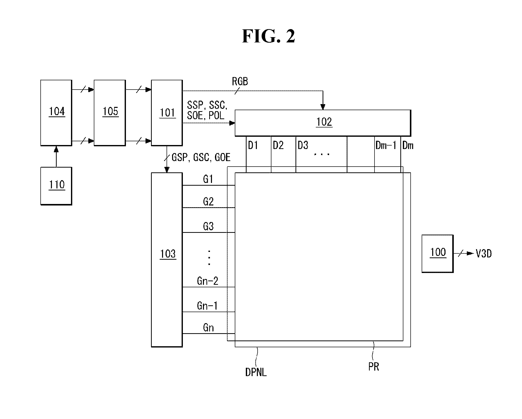
A stereoscopic image display includes a liquid crystal display panel including a plurality of pixels, each of which is divided into a main pixel unit and an switchable black stripe, a data driving circuit, a gate driving circuit, and a 3D control voltage generation circuit, which supplies AC voltages, of which phases are sequentially shifted, to a plurality of 3D control lines in a 3D mode.

Description

CROSS-REFERENCE TO RELATED APPLICATIONS[0001]This application claims priority under 35 U.S.C. 119(a) of Korean Patent Application No. 10-2011-0101311, filed on Oct. 5, 2011, which is incorporated by reference in its entirety.BACKGROUND[0002]1. Technical Field[0003]The embodiments disclosed herein relate to a stereoscopic image display.[0004]2. Discussion of the Related Art[0005]A glasses type stereoscopic image display for displaying three-dimensional (3D) images is classified into a polarized glasses type stereoscopic image display and a shutter glasses type stereoscopic image display. The polarized glasses type stereoscopic image display requires a polarization separation device, such as a patterned retarder, to be attached to a display panel. The patterned retarder separates polarized light of a left eye image and a right eye image displayed on the display panel. A viewer wears polarized glasses when viewing a stereoscopic image on the polarized glasses type stereoscopic image di...

Claims


Application Information

Patent Timeline
Patent Type & Authority Patents(United States)
IPC IPC(8): G09G3/36H04N13/04G09G3/00G02B27/22G02B27/26G09G5/00G02B30/25
CPCG09G3/003G02B27/2264G02B27/26G09G3/3648H04N13/0434H04N13/0454G09G2300/0426G09G2300/0443G09G2300/0876G02B30/24G02B30/25H04N13/337H04N13/359G09G3/36
Inventor KIM, JEONGKIBAEK, SEUNGHOKIM, JOOAH
Owner LG DISPLAY CO LTD
Learn More