Method of eliminating conductive drill parasitic influence on the measurements of transient electromagnetic components in MWD tools

a technology of transient electromagnetic components and parasitic influence, which is applied in the field of reducing the effect of conductive drill pipes, can solve the problems of reducing the sensitivity of the measured em field, introducing a metal drill pipe close, and limited tool groups

Active Publication Date: 2006-12-19
BAKER HUGHES HLDG LLC
View PDF9 Cites 70 Cited by
  • Summary
  • Abstract
  • Description
  • Claims
  • Application Information

AI Technical Summary

Problems solved by technology

This group of tools is naturally limited by, among other things, their applicability to only high resistivity formations and the power available down-hole.
The major problem associated with the MWD environment is the introduction of a metal drill pipe close to the area being measured.
This pipe produces a very strong response and significantly reduces the sensitivity of the measured EM field to the effects of formation resistivities and remote boundaries.
The sensitivity of such a tool to remote boundaries is low.
A disadvantage of both MPR and HDIL methods is that the primary source of induction from the transmitter is always present during the time frame in which the receivers are obtaining measurements from the formation, thereby distorting the intended signal.
Although the formation signal dominates at the late stage, it is also very small, and reliable measurement can be difficult.
Besides having limited resolution with respect to an oil / water boundary, such a system is very long (up to 10–15 m) which is not desirable and convenient for an MWD tool.

Method used


Image

  • Method of eliminating conductive drill parasitic influence on the measurements of transient electromagnetic components in MWD tools
  • Method of eliminating conductive drill parasitic influence on the measurements of transient electromagnetic components in MWD tools
  • Method of eliminating conductive drill parasitic influence on the measurements of transient electromagnetic components in MWD tools

Examples


first embodiment

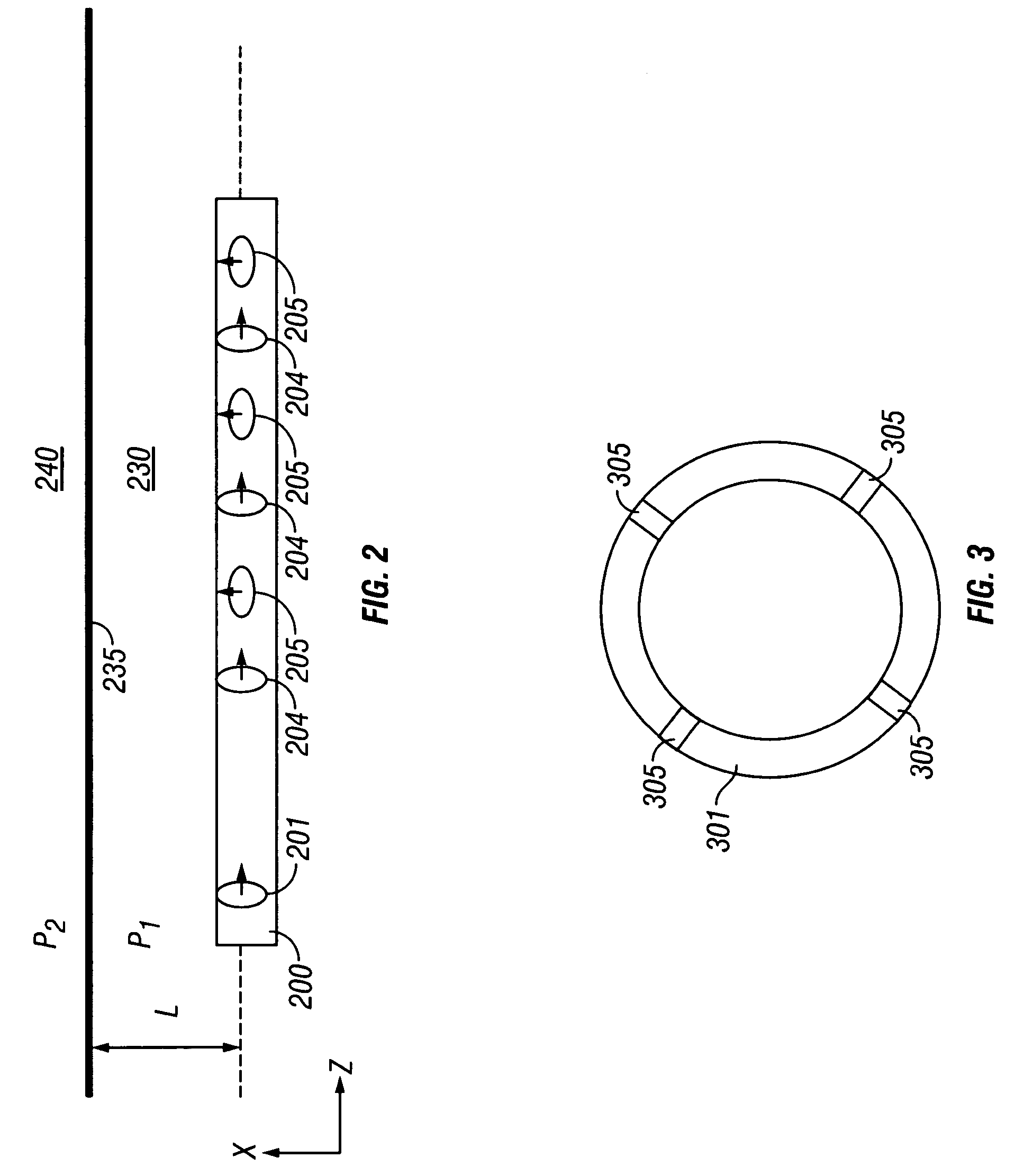
[0038]Although FIG. 2 illustrates one configuration of transmitter and receiver, a variety of transmitter receiver configurations can be used in the present invention. In the MWD transient tool, a Z-directed transmitter coil can be positioned along the damping portion, and a receiver coil pair comprising an X-directed a Z-directed receiver coil pair is axially displaced from the Z-directed transmitter coil. The receiver pair is typically placed at a distance of from 0 m to 10 m from the transmitter, also on the damping portion. A transmitter-receiver distance less than approximately 2 m from the transmitter further enables geosteering. The term geosteering refers to control of the drilling direction of the BHA based upon determined distances from an interface in the earth formation. Typically, in geosteering, it is desired to maintain the drilling of the borehole at a desired depth below a fluid interface such as an oil / water, gas / oil or gas / water interface. Alternatively, geosteeri...

fourth embodiment

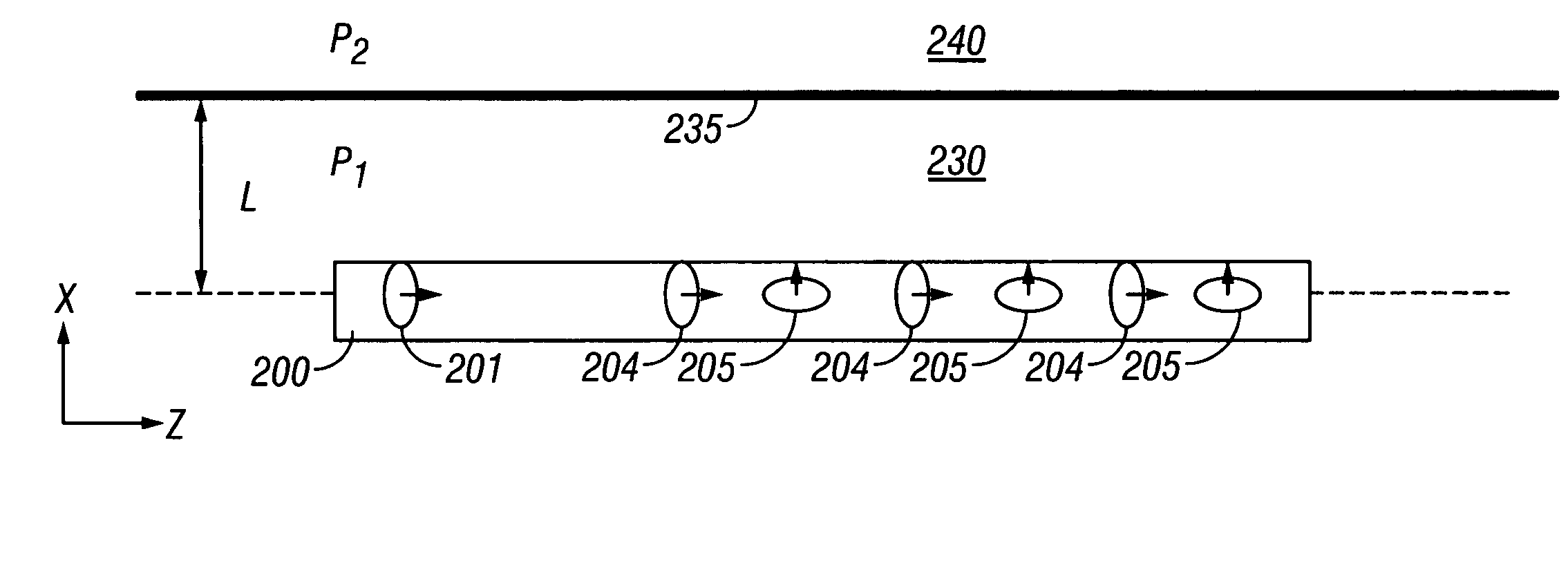
[0041]In the MWD transient tool, a Z-directed transmitter coil and an array of X- and Z-directed coils can be placed along the damping portion of the pipe at a distance of from 0 m to 10 m from the transmitter coil. The damping portion can typically extend from 10 to 20 m in length with receiver array extending a distance up to approximately 10 m from the transmitter.

[0042]Additionally, the damping portion of the pipe can further comprise a combination of cuts in the pipe and magnetic material with high magnetic permeability covering the pipe. For example, a periodic sequence of pipe elements can be made in which, for example, a first 1 m of the pipe has cuts and the next 1 m of the pipe is covered by magnetic material. This 2 m long pipe-element can be repeated. A typical number of repetitions can be, for example, 10 times. Also, the damping portion can comprise only a magnetic covering to enable suppression of an eddy current signal.

[0043]The drilling tool 200 of FIG. 2 lies horiz...


PUM


Abstract

A transmitter on a bottomhole assembly (BHA) is used for generating a transient electromagnetic signal in an earth formation. A receiver on the BHA receives signals that are indicative of formation resistivity and distances to bed boundaries. The transmitter and receiver may have axes that are parallel to or inclined to the axis of the BHA. The transmitter and the receiver are on a tubular on a damping portion of the BHA that includes cuts for attenuating eddy currents. The damping portion may include non conducting material such as a ferrite on the outer surface.

Description

BACKGROUND OF THE INVENTION[0001]1. Field of the Invention[0002]The invention relates to the field of electromagnetic induction well logging. More specifically, the present invention is a method of reducing effects of conductive drill pipes on resistive signals in transient electromagnetic phenomena.[0003]2. Description of the Related Art[0004]Electromagnetic induction resistivity instruments can be used to determine the electrical conductivity of earth formations surrounding a wellbore. An electromagnetic induction well logging instrument is described, for example, in U.S. Pat. No. 5,452,761 issued to Beard et al. The instrument described in the Beard '761 patent includes a transmitter coil and a plurality of receiver coils positioned at axially spaced apart locations along the instrument housing. An alternating current is passed through the transmitter coil. Voltages which are induced in the receiver coils as a result of alternating magnetic fields induced in the earth formations ...

Claims


Application Information

Patent Timeline
Patent Type & Authority Patents(United States)
IPC IPC(8): E21B43/00A23B4/03A23C15/04G01V3/28
CPCA23B4/031G01V3/28
Inventor ITSKOVICH, GREGORY B.
Owner BAKER HUGHES HLDG LLC
Why Eureka
Try Eureka