

Droplet ejection apparatus and ejection failure recovery method
- Summary
- Abstract
- Description
- Claims
- Application Information
AI Technical Summary
Benefits of technology
Problems solved by technology
Method used
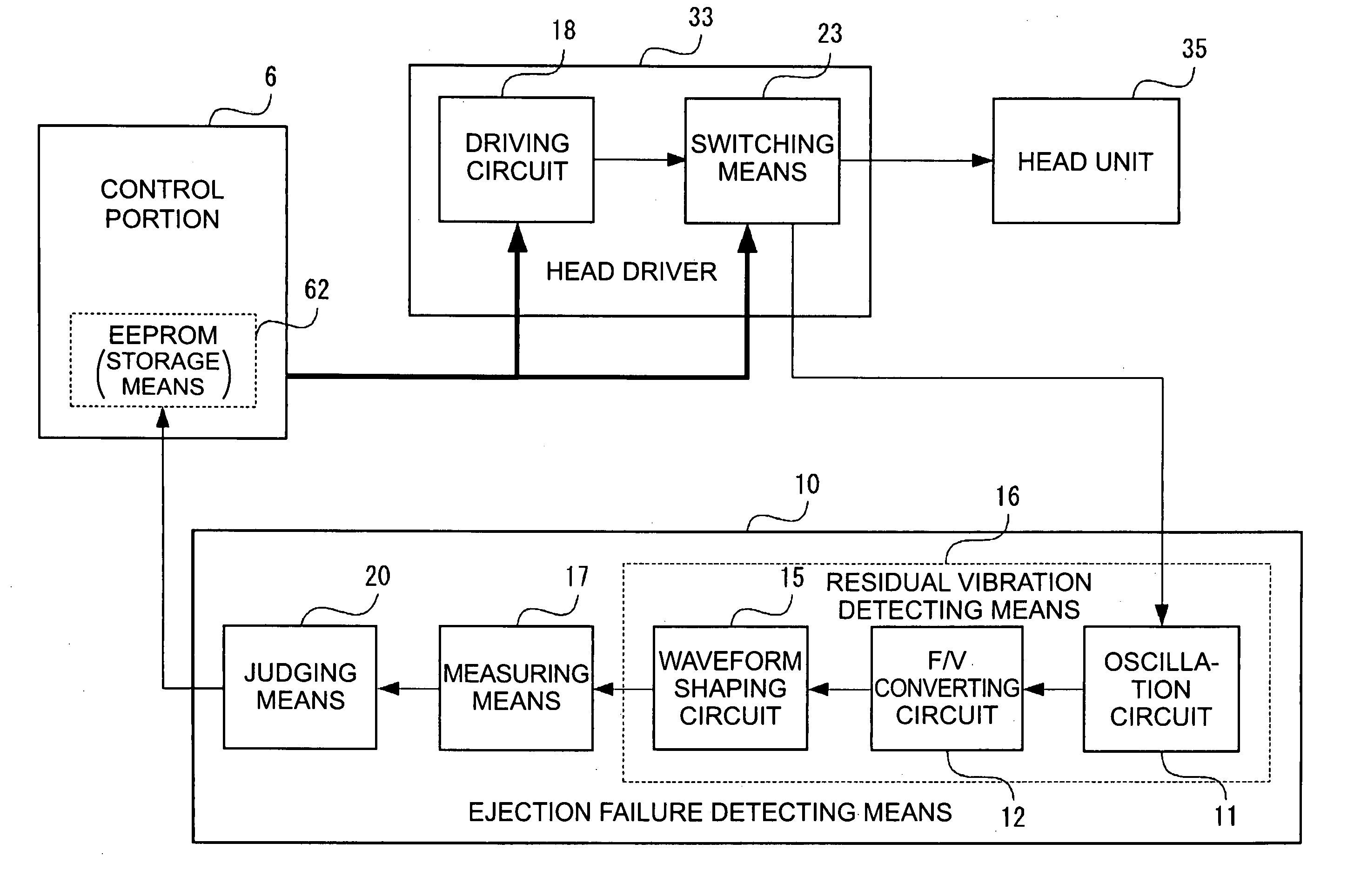
Image

Examples
first embodiment
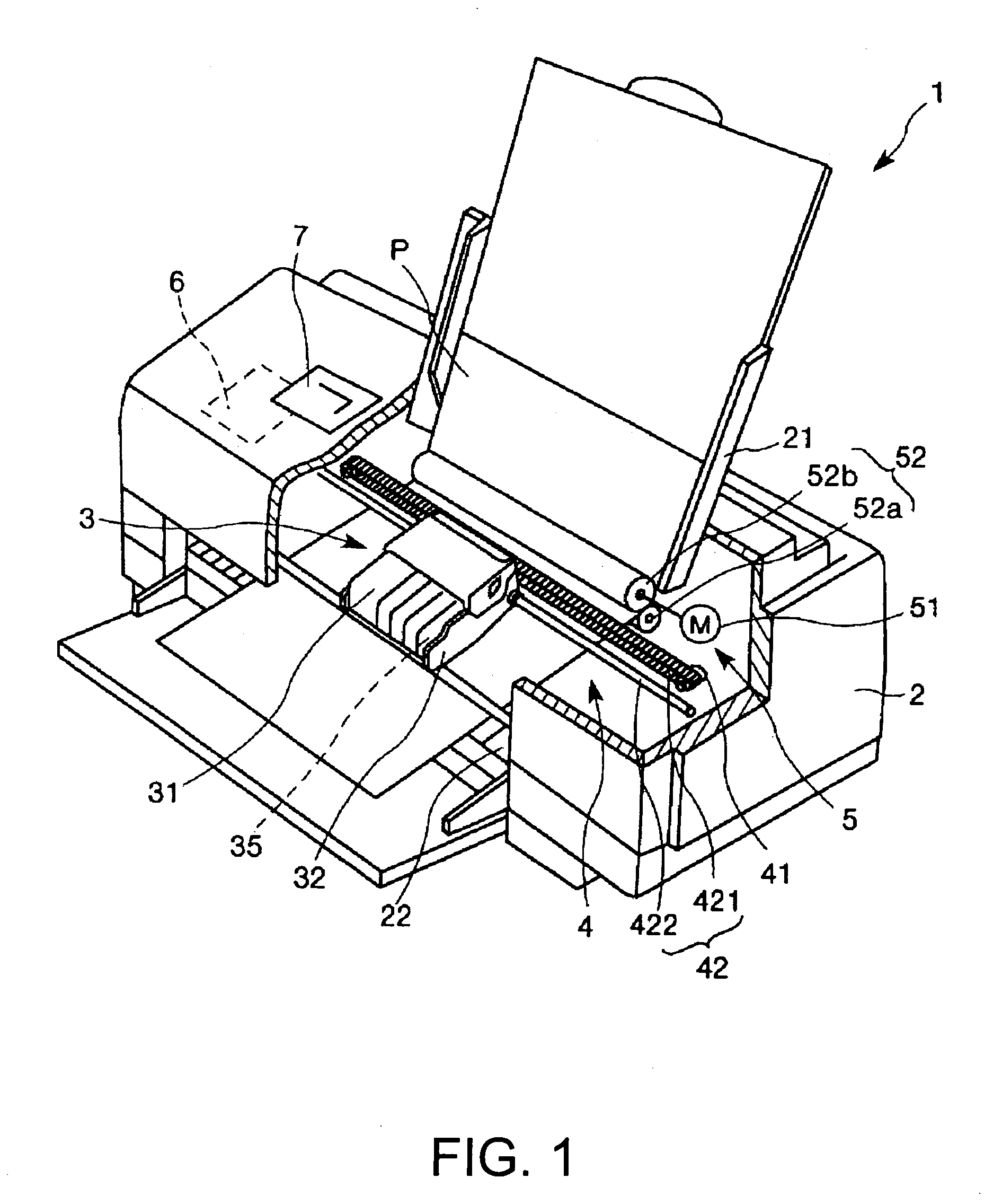
[0158]FIG. 1 is a schematic view showing the configuration of an ink jet printer 1 as one type of a droplet ejection apparatus according to a first embodiment of the invention. Hereinafter, the upper side and the lower side of FIG. 1 are referred to as “top” and “bottom”, respectively. First, the configuration of the ink jet printer 1 will be described.
[0159]The ink jet printer 1 shown in FIG. 1 includes an apparatus main body 2. A tray 21, on which a recording sheet P is placed, is provided rearward of the top, a sheet discharge port 22, through which the recording sheet P is discharged, is provided frontward of the bottom, and an operation panel 7 is provided on the top surface.
[0160]The operation panel 7 comprises, for example, a liquid crystal display, an organic EL display, an LED lap, etc., and is provided with a display portion (not shown) to display an error message or the like and an operation portion (not shown) comprising various kinds of switches or the like. The display...
second embodiment
[0379]Examples of other configurations of the ink jet head of the invention will now be described. FIG. 44 through FIG. 47 are cross sections schematically showing examples of other configurations of the ink jet head (head unit). Hereinafter, an explanation will be given with reference to these drawings; however, differences from the embodiment described above are chiefly described, and the description of the similar portions is omitted.
[0380]An ink jet head 100A shown in FIG. 44 is of a type that ejects ink (liquid) within a cavity 208 through a nozzle 203 as a diaphragm 212 vibrates when a piezoelectric element 200 is driven. A metal plate 204 made of stainless steel is bonded to a nozzle plate 202 made of stainless steel in which the nozzle (hole) 203 is formed, via an adhesive film 205, and another metal plate 204 made of stainless steel is further bonded to the first-mentioned metal plate 204 via an adhesive film 205. Further, a communication port forming plate 206 and a cavity...
third embodiment
[0395]An example of still another configuration of the ink jet head of the invention will now be described. FIG. 48 is a perspective view showing the configuration of a head unit 35 of this embodiment. FIG. 49 is a cross section of the head unit 35 (ink jet head 100H) shown in FIG. 48. Hereinafter, an explanation will be given with reference to these drawings; however, differences from the embodiments above will be chiefly described, and the description of the similar portions is omitted.
[0396]The head unit 35 (ink jet head 100H) shown in FIG. 48 and FIG. 49 is of a so-called film boiling ink jet type (thermal jet type), and is provided with a supporting plate 410, a substrate 420, an outer wall 430, partition walls 431, and a top plate 440, which are bonded to each other in this order from bottom to top of FIG. 48 and FIG. 49.
[0397]The substrate 420 and the top plate 440 are placed so that they are spaced apart by a predetermined interval with having in between the outer wall 430 a...
PUM
 Abstract
Description
Claims
Application Information